Haier HDW15U3S1 Built Under Dishwasher


Built-under Dishwasher
HDW15U3S1 & HDW15U3B1 models
INSTALLATION GUIDE NZ AU

| General | Details |
|---|---|
| Name | Haier HDW15U3S1 Built Under Dishwasher |
| Make | Haier |
| Language | English |
| Filetype | PDF (Download) |
| File size | 0.85 MB |


Haier HDW13V1S1 Dishwasher

Haier HDW15V3S1 Satina Dishwasher

Haier HDW10F1S1 300 Series Compact Dishwasher

Haier HDW15V2B2 Dishwasher

Haier HDW13G1W Dishwasher

Haier HDW15V2S1 Dishwasher

Haier HDW13G1X Dishwasher

Haier HDW10F1S1 Compact Dishwasher

Haier HDW13F0W1 Hygiene Dishwasher

Haier HDW13F0B1 Dishwasher
Haier HDW15U3S1 Built Under Dishwasher Overview
Summary of Contents
- Page 1: Built-under dishwasher HDW15U3S1 & HDW15U3B1 models. Installation guide.
- Page 2: Page 2
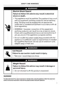
- Page 3: Safety and warnings Do not repair or replace any part of the appliance unless specifically recommended in this guide. Ensure all water connections are turned off. The dishwasher must be installed to allow for future removal from the enclosure if service is required. This dishwasher is manufactured for indoor use only. Failure to install the dishwasher correctly could invalidate any warranty or liability claims. Do not operate this appliance if it is damaged, malfunctioning, partially disassembled or has missing or broken parts. Do not install or store the dishwasher where it will be exposed to temperatures below freezing or exposed to weather. This appliance must be earthed. Installation must comply with your local building and electricity regulations. At the completion of the dishwasher installation, the installer must perform the final checklist.
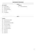
- Page 4: Components required include various tools and parts. Tools not supplied include a powered driver, 4mm/6mm Allen key, Phillips screwdriver, flat-head screwdriver, and box cutter. Supplied tools include a 5mm Allen key. Parts supplied consist of moisture protection tape, toe kick brackets (2), pre-finished toe kick assembly, drain hose support, screws of various sizes, washers, sound seal, and spacers.
- Page 5: Overall height: 820 - 880 mm Overall width: 597 mm Overall depth: 574 mm Not required for single product installation.
- Page 6: Cabinetry dimensions include overall height, overall width, and minimum depth of the cavity. The overall height of the cavity is between 820 and 880 mm. The overall width of the cavity is 600 mm. The minimum depth of the cavity is 580 mm. The dimensions may vary depending on the height of the feet.
- Page 7: Minimum clearance to adjacent cupboard door Minimum clearance to corner cupboard
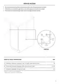
- Page 8: Service access We recommend locating the service holes on either side of the dishwasher as shown. If the holes are created through wood, ensure the edges are smooth and rounded. If the holes are created through metal, ensure an edge protector is fitted. Maximum distance between rear of cavity and service hole. Maximum distance between floor and service hole. Minimum diameter of service hole. Based on a cabinetry depth of 580mm. Depending on adjustment of leveling feet.
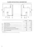
- Page 9: Plumbing and electrical considerations Length of drain hose Length of power cord Length of inlet hose Distance from floor to top of hose support Minimum distance from floor to end of drain hoses Minimum inlet hose radius Standpipe install illustrated. Distance is the same for all plumbing installs.
- Page 10: Plumbing and electrical considerations Your services can be installed to either the left-hand or right-hand side of the product in an adjacent cabinet. The drain hose should not extend more than 4m. A longer drain hose will cause reduced performance. The dishwasher should not be connected to a water system where there is no temperature control, unless the system is fitted with a suitable tempering valve. The dishwasher must not be connected to an undersink high-pressure push-through hot water system, as damage to the system will result. Maximum water temperature: 60°C. Ensure water connection complies with local plumbing regulations. Power voltage: 220–240V (50Hz). Maximum current intensity: 10A. Total absorbed power: 1720–2050W. This dishwasher has anti-flood protection, which will stop the water flowing in the event of a leak within the machine.
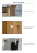
- Page 11: Prior to installation, unpack the product and dispose of packaging responsibly. Ensure all minimum cabinetry and service specifications have been met and that all services will be accessible after installation. Remove the install kit, any internal packaging, all rubber bands, and all tape.
- Page 12: Ensure cabinetry floor is free from bumps and obstructions that could prevent the dishwasher from sliding into the cavity. Align the supplied moisture protection tape to the cabinetry as shown. Ensure this area is free of debris before carefully applying the tape to the surface.
- Page 13: Push into cavity Using a flat bladed screwdriver, turn to raise the leveling feet. Level the rear, outside legs first followed by the front legs. Do not adjust the rear middle leg yet. Remove both screw covers before partially pushing the product into the cavity. Pull the hoses through as you push to avoid crushing or twisting them. Take care not to bend the legs. Push the product from the outside edges to avoid door damage. Check the product sits level within the cavity. If required, the rear middle leg can be adjusted from the front of the product using a 5mm Allen key.
- Page 14: Select desired spacer width and cut to size. Remove adhesive and fit two spacers to each side of the product. Push the product into the cavity from the outside edges.
- Page 15: Secure to cavity. Loosely fit side fixing screws. Adjust the dishwasher within the cavity if needed. Tightly secure in place. Replace the screw covers. Secure to benchtop using screws if possible.
- Page 16: Secure to cavity Align both sound seal sheets to the base of the dishwasher. If required, trim excess felt. Ensure door swing is unobstructed before securing the seals using the provided washers and screws.
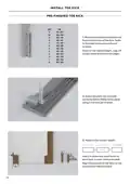
- Page 17: Install toe kick Pre-finished toe kick Measure the distance between the floor and the base of the door. Refer to the table and mark out the cut location. Score at the marked height, snap off excess material and smooth edges. Ensure brackets are oriented correctly before fitting to the panel using screws. Measure the toe kick depth. Use Z to determine which tooth to bend back on each toe kick bracket. Align the brackets to the slots on the product and slide into place.
- Page 18: Install toe kick Custom toe kick Mark the pilot hole locations for each bracket. Measure the centre of the panel and mark 237mm to each side. To determine the height of the brackets, measure the height of the lowest bracket hole against the toe kick panel. Ensure brackets are oriented correctly before fitting to the panel using 2 x screws per bracket. Measure the toe kick depth: toe kick recess, panel thickness, toe kick depth. Use Z to determine which tooth to bend back on each toe kick bracket. Align the brackets to the slots on the product and slide into place.
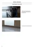
- Page 19: Align toe kick to product and ensure all door swing clearances have been met. Fit panel to surrounding cabinetry.
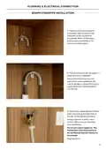
- Page 20: Plumbing & electrical connection Install the drain hose support to the back wall, as close to the underside of the countertop as possible. Pull the hose through the support guide and rest in standpipe. Ensure the drain hose does not extend into water retained in the trap; an air gap is required to prevent waste water from siphoning back into the tub. Ensure the rubber washer is fitted when connecting the inlet hose to the tap. Hand-tighten into place. Using a spanner or pliers, turn a further 180° to secure. Avoid over-tightening. Do not turn water supply on. The dishwasher must be powered on for the flood protection feature to be enabled. Plug product in.
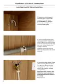
- Page 21: Plumbing & electrical connection Install the drain hose support to the back wall, as close to the underside of the countertop as possible. Pull the hose through the drain hose support before threading the hose clamp onto the hose and fitting to the sink trap. Ensure hose is routed straight to the trap. Unplug or drill out the waste tee before securing joiner to sink trap or waste tee. Ensure the rubber washer is fitted when connecting the inlet hose to the tap. Hand-tighten into place and use a spanner or pliers to turn a further 180° to secure. Avoid over-tightening. Do not turn water supply on; the dishwasher must be powered on for the flood protection feature to be enabled. Plug product in.
- Page 22: Installer checklist to be completed by the installer. Check all parts are installed correctly and are secure. Ensure all packaging, tape and rubber bands have been removed. Ensure all clearance gaps have been maintained. Ensure the dishwasher is securely fastened to the cabinetry and door opens and closes freely with no resistance. Ensure the panel is fitted correctly to the dishwasher. Check the spray arm is in place, mounted correctly and rotates freely. Ensure any knock-outs or plugs in the drain connection have been drilled out and the drain connection has been made. The drain hose joiner must not support the weight of excess hose material. Ensure the inlet hose has the supplied rubber washer fitted and that it is tightened.
- Page 23: Turn power and water supply on and open the dishwasher. Press to select Rinse. Press to begin the cycle. After the Rinse cycle has finished, ensure the dishwasher has run and drained correctly.
- Page 24: Complete and keep for safe reference. Model. Serial no. Purchase date. Purchaser. Dealer address. Installer’s name. Installer’s signature. Installation company. Installation date.
- Page 25: Page 25

ARDESTO DWMF-V458SMHW3 Dishwasher

AEG FSK76748P Dishwasher

FISHER PAYKEL DD60D2HNX9 Built Under Dishwasher

FISHER AND PAYKEL DW60UC4X2 Contemporary Built Under Dishwasher

FISHER PAYKEL DD60DCHX9 Dishwasher

GE APPLIANCES G034 Dishwasher

KitchenAid KDTE304RBS Level Jet Rack Dishwasher

gorenje GV673B66 Dishwasher

Fisher and Paykel DW60U6I1 Integrated Dishwasher

BOSCH SHP87P Dishwasher