Home > FISHER and PAYKEL > FISHER AND PAYKEL DW60FC1X2 Dishwasher
FISHER AND PAYKEL DW60FC1X2 Dishwasher


DISHWASHER
CONTEMPORARY
DW60FC1X2, DW60FC1B2, DW60FC1X3, DW60FC2X2,
DW60FC2B2, DW60FC2X3, DW60FC4X2, DW60FC4B2 and
DW60FC4X3 models
INSTALLATION GUIDE
NZ AU

| General | Details |
|---|---|
| Name | FISHER AND PAYKEL DW60FC1X2 Dishwasher |
| Make | FISHER and PAYKEL |
| Language | English |
| Filetype | PDF (Download) |
| File size | 0.75 MB |


FISHER and PAYKEL DD60SCTX9 Dishwasher

FISHER and PAYKEL DD60DDFHX9 Dishwasher

FISHER and PAYKEL DD24SCTB9 N Dishwasher

FISHER and PAYKEL DD60SCTW9 Dishwasher

FISHER and PAYKEL DD60SDFTX9 Dishwasher

Fisher and Paykel DW24UT2I2 Dishwasher

FISHER AND PAYKEL DD24SHTI9N Dishwasher

FISHER AND PAYKEL DD60SDFHTX9 Tall Dishwasher

FISHER AND PAYKEL DD24DTI9 N Dishwasher

FISHER AND PAYKEL DD24STI9 Dishwasher

FISHER AND PAYKEL DW60FC1X2 Dishwasher Overview
Summary of Contents
- Page 1: Dishwasher Contemporary Models: DW60FC1X2, DW60FC1B2, DW60FC1X3, DW60FC2X2, DW60FC2B2, DW60FC2X3, DW60FC4X2, DW60FC4B2, DW60FC4X3 Installation guide NZ AU
- Page 2: Safety and warnings Electric shock hazard Cut hazard Failure to follow this advice may result in electrical shock or death. Failure to use caution could result in injury. Take care – panel edges are sharp. This appliance must be earthed. Improper connection of the equipment-earthing conductor can result in a risk of electric shock. Do not attempt to lift this product unassisted. Do not modify the power supply plug provided with the appliance.
- Page 3: Safety and warnings Failure to install the custom panels correctly could invalidate any warranty or liability claims. To reduce the risk of fire, injury to persons or damage when using the appliance, follow the important safety instructions listed below. Installation of this dishwasher requires basic mechanical and electrical skills. Be sure to leave these instructions with the customer. At the completion of the dishwasher installation, the installer must perform the final checklist. Do not repair or replace any part of the appliance unless specifically recommended in this guide. Ensure all water connections are turned off. The dishwasher must be installed to allow for future removal from the enclosure if service is required. Do not operate this appliance if it is damaged, malfunctioning, partially disassembled or has missing or broken parts. This appliance must be earthed.
- Page 4: Components required include various parts and tools. Keep all packing materials until the unit has been inspected. Inspect the product to ensure there is no shipping damage. Contact the dealer or retailer if any damage is detected. Fisher & Paykel is not responsible for shipping damage. Supplied tools include a powered driver, cross-head screwdriver, and flat-head screwdriver. Drain hose support and inlet hose are also included. Moisture protection tape and spacers are part of the supplied components. A 5mm Allen key is included in the package.
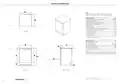
- Page 5: Product dimensions include overall height, width, and depth of the product. Models listed are DW60FC1X2, DW60FC1B2, DW60FC1X3, DW60FC2X2, DW60FC2B2, DW60FC2X3, DW60FC4X2, DW60FC4B2, and DW60FC4X3. Overall height of the product is between 850 - 895 mm. Overall width of the product is 610 mm. Overall depth of the product is 597 mm. Minimum clearances for corner cupboard are specified. Minimum inside height of cavity with the top panel in place is 850 - 895 mm. Minimum inside width of cavity is 600 mm. Minimum overall depth of cavity is 605 mm. Dimensions may vary by ±2mm (1/16).
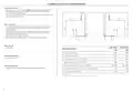
- Page 6: Cabinetry dimensions and clearances are important for proper installation. It is recommended to leave the top cap installed for better moisture damage protection. Connections can be located in an adjacent cabinet on either side of the dishwasher. Minimum inside height with top panel in place is 850 - 895 mm. Minimum clearance to adjacent cupboard door is 820 - 865 mm. Minimum clearance to corner cupboard with top panel removed is 600 mm. Recommended height of adjacent cabinetry is 713 - 794 mm. Height of toe kick area is 65 - 200 mm. For more information on service requirements, refer to 'Plumbing & electrical considerations' and 'Cabinetry preparation'. The top panel may be removed to suit underbench cavity height.
- Page 7: Plumbing and electrical considerations Your services can be installed to either the left-hand or right-hand side of the product in an adjacent cabinet. The drain hose should not extend more than 4m. A longer drain hose will cause reduced performance. The dishwasher should not be connected to a water system where there is no temperature control, unless the system is fitted with a suitable tempering valve. The dishwasher must not be connected to an undersink high-pressure push-through hot water system, as damage to the system will result. Ensure water connection complies with local plumbing regulations. Electrical requirements: 230V, 50Hz, 10A. When powered, this product has anti-flood protection features.
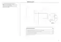
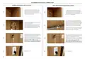
- Page 8: Service access We recommend locating the service holes on either side of the dishwasher as shown. If the holes are created through wood, ensure the edges are smooth and rounded. If the holes are created through metal, ensure an edge protector is fitted. Maximum distance between rear of cavity and service hole. Maximum distance between floor and service hole. Minimum diameter of service hole. Based on a cabinetry depth of 580mm. Depending on adjustment of leveling feet.
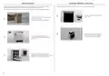
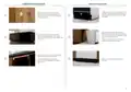
- Page 9: Top panel removal (optional) Unpack product Always be careful with the hoses and power cord at the back of the dishwasher. The moisture protection tape must be used when removing the top panel. Never lift the dishwasher from the door handle or top plate. Unscrew the top panel at the rear either side. Cut straps, lift carton off product and remove the top cap. Slide forward 20-30mm, then lift upwards. Ensure moisture tape is installed if removing top panel. Lift the product to remove from the base packaging, two people are required. Remove the install kit, any internal packaging, all rubber bands and all tape that are securing cords and hoses.
- Page 10: Cabinetry preparation is essential for installation. Level the rear legs first, followed by the front legs. Ensure all minimum cabinetry service specifications have been met. Make sure all services will be accessible after installation. Push the product into position while pulling the hoses through. Avoid crushing or twisting the hoses during installation. Ensure the cabinetry floor is free from bumps and obstructions. Push the product from the outside edges to avoid door damage. Align the supplied moisture protection tape to the cabinetry. Check that the product sits level within the cavity.
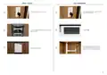
- Page 11: Plumbing & electrical connection Install the drain hose support to the back wall, as close to the underside of the countertop as possible. Refer to 'Plumbing & electrical considerations' for minimum install heights. Ensure hose is routed straight to the joiner, remove any excess drain hose. Ensure the drain hose does not extend into water retained in the trap; an air gap is required to prevent waste water from siphoning back into the tub. Do not shorten the inlet hose. Ensure the rubber washer is fitted to the coupling before connecting the inlet hose to the tap. Hand-tighten into place. Using a spanner or pliers, turn a further 180° to secure, avoiding over-tightening. Do not turn water supply on. The dishwasher must be powered on for the flood protection feature to be enabled. Plug product in.
- Page 12: Final checks Test operation Turn power and water supply on and open the dishwasher. Power and water is turned on. Select rinse. All internal packaging and rubber bands are removed. After the rinse cycle has finished, ensure the dishwasher has run and drained correctly. Check for leaks. Gaps are consistent.
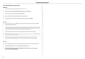
- Page 13: Installer checklist To be completed by the installer Installation Check all parts are installed correctly and are secure. Ensure all packaging, tape and rubber bands have been removed. Ensure all clearance gaps have been maintained. Ensure door opens and closes freely with no resistance. Check the spray arm is in place, mounted correctly and rotates freely. Plumbing Ensure any knock-outs or plugs in drain connection have been drilled out and drain connection has been made. The drain hose joiner must not support the weight of excess hose material. Ensure inlet hose has supplied rubber washer fitted, and that it is tightened. If connecting the drain hose to the sink trap, ensure the high loop is a minimum 150mm higher than the drain hose joiner. Electrical Ensure all electrical tests have been conducted in accordance with local regulations.

BOSCH SMS2HMI04E Dishwasher

BOSCH SMV2ITX09E Dishwasher

Midea MDT24X2APR Dishwasher

LG SDWD24P3 Dishwasher
FISHER PAYKEL DW60FC2X3 Dishwasher

SAMSUNG DW80BB70 Series Dishwasher

FISHER PAYKEL DD24DCHTX9 N Sanitize Dishwasher

sirius MDWBI6053 Dishwasher

BOSCH SHV 6800 Dishwasher

GRUNDIG GSV 428420 Dishwasher