SAMSUNG DW80BB70 Series Dishwasher


Dishwasher
Installation manual
DW80BB70* Series, DW80B70* Series, DW80B60* Series

| General | Details |
|---|---|
| Name | SAMSUNG DW80BB70 Series Dishwasher |
| Make | Samsung |
| Language | English |
| Filetype | PDF (Download) |
| File size | 3.96 MB |
 (1 votes, average: 5.00 out of 5)

SAMSUNG DW80N3030UW Front Dishwasher

SAMSUNG DW90F89 Dishwasher

SAMSUNG DW80BB70 Dishwasher

SAMSUNG DW50T6060U Dishwasher

SAMSUNG DW80CB5450 Dishwasher

Samsung DW60M5062 Dishwasher

Samsung DW60 7 Series Dishwasher

SAMSUNG DW9000F Dishwasher

SAMSUNG DW60R2014 Wide 12 Place Dishwasher

SAMSUNG DW60H9950FW-SA Dishwasher

SAMSUNG DW80BB70 Series Dishwasher Overview
Summary of Contents
- Page 1: Dishwasher installation manual DW80BB70* Series, DW80B70* Series, DW80B60* Series
- Page 2: Safety instructions Important safety instructions Before using your dishwasher Installation Product dimensions Cabinet dimensions Specifications Scan the QR code to view our helpful installation videos.
- Page 3: Safety instructions are crucial for the proper use of the dishwasher. Warnings and cautions highlight potential hazards that may result in severe personal injury or death. It is important to use common sense, caution, and care during installation, maintenance, and operation. Samsung is not liable for damages resulting from improper use. Basic safety precautions should be followed to reduce the risk of fire, explosion, electric shock, or personal injury. Warning signs are intended to prevent injury to users and others. Installation instructions are meant for qualified installers only. Keep safety instructions in a safe place for future reference. If problems arise during installation, immediate assistance should be sought. These instructions are designed to ensure safe and effective use of the dishwasher.
- Page 4: Safety instructions are crucial for the proper use of the appliance. California Proposition 65 Warning indicates potential cancer and reproductive harm. Read all instructions before using the appliance. Install and store the dishwasher away from exposure to weather. Do not install the dishwasher near electrical components or open flames. Avoid installing the dishwasher on carpet to prevent fire hazards. Ensure the dishwasher is not placed in locations where water may freeze. The dishwasher must be properly grounded to avoid electrical hazards. All wiring and grounding must comply with the applicable electrical code. Two or more people are needed to move the dishwasher safely.
- Page 5: Make sure to use a new water supply line. Old lines are susceptible to breakage and may cause property damage due to water leakage. The dishwasher must be connected to a hot water supply with a temperature between 120 °F (49 °C) and 149 °F (65 °C). Temperature should not exceed 149 °F (65 °C) to prevent damage to dishes. Ensure that the water supplied to the dishwasher does not freeze. Certified residential dishwashers are not intended for licensed food establishments. Do not use the dishwasher until it is correctly installed. Do not push down on the dishwasher door when it is open. Electrically ground the dishwasher. Do not use an extension cord. The installer must ensure that the dishwasher is completely enclosed at the time of installation.
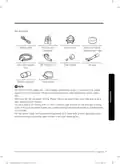
- Page 6: Installation Be sure that you or your installer follow these instructions closely so that the new dishwasher works properly and that you are not at risk of injury when washing dishes. Check the parts and tools Before starting on the installation, prepare all the necessary tools and parts required to install the dishwasher. This will save installation time and simplify the installation process. Parts required Provided with the dishwasher. Check when you unbox the dishwasher.
- Page 7: For the hot water supply line, we strongly recommend using 3/8 minimum O.D. copper tubing with a compression fitting or a flexible stainless steel braided hot water supply line. Do not use plastic tubing. Plastic tubing can deteriorate over time and cause a leak inside the tube fitting. You also need a 90° fitting with 3/4 N.P.T. external pipe threads on one end and a fitting sized to fit your hot water supply line. For the power cable, we recommend a jacketed 12-2 cable with ground. Some local codes may require the cable to have a BX style metal jacket.
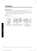
- Page 8: Installation Tools required Electric drill Safety glasses Wire stripper Gloves Pliers Flashlight Nipper Adjustable wrench Tape measure
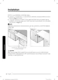
- Page 9: New installation requires most of the work to be done before moving the dishwasher into place. When replacing an old dishwasher, check existing connections for compatibility with the new unit. Select a location with a solid floor that can support the dishwasher's weight. The location should be near a sink with easy access to water supply, drain, and electrical outlet. For proper drain operation, the dishwasher should be installed within 9.8 ft (3 m) of the sink. Ensure the location allows for easy loading of dishes into the dishwasher. There must be sufficient space for the dishwasher door to open easily and for clearance between the dishwasher and cabinet sides. If installed in a corner, the dishwasher should be more than 2 in. (50 mm) from adjacent walls or cabinets. The wall at the back must be free of obstructions. Make sure the cabinet for the dishwasher is secured to the floor to minimize noise during operation.
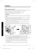
- Page 10: Installation If this is a new installation, follow these steps: Using a 2 1/2 inch hole saw, cut a hole into the side of the cabinet that holds the sink. If the base inside the sink cabinet is raised above the kitchen floor and is higher than the connections on the dishwasher, make a hole in the base inside the cabinet and in the cabinet side. Depending on where your electrical outlet is, you may need to cut a hole in the opposite cabinet side. Make sure the edges of the cabinet hole are smooth before you insert the drain hose through the hole. Sharp edges from the cabinet hole may cause damage to the drain hose, resulting in a leak from the hose.
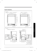
- Page 11: Product dimensions Front view Side view You must arrange the water supply line, power cable and drain hose in the space behind the dishwasher.
- Page 12: Installation You must arrange the water supply line, power cable, and drain hose in the space behind the dishwasher. This dishwasher is designed to be enclosed on the top and on both sides by a standard residential kitchen cabinet unit. The installation cabinet must be clean and free of any obstructions. The cabinet must be at least 24 inches wide, 24 inches deep, and 34 1/8 inches high. For the front door of the dishwasher to be flush with the leading edge of the countertop, the countertop must be at least 25 inches deep.
- Page 13: Check water supply requirements and cautions. The hot water supply line pressure must be between 20 - 120 psi (140 - 830 kPa). Adjust the water heater to deliver water between 120 °F (49 °C) - 149 °F (65 °C). The dishwasher must be connected to a hot water supply between 120 °F (49 °C) - 149 °F (65 °C). This temperature range provides the best washing result and shortest cycle time. Temperature should not exceed 149 °F (65 °C) to prevent damage to dishes. Ensure that the water supply valve is turned off before connecting the hot water supply line to the dishwasher. Seal the hot water supply line connections using teflon tape or sealing compound to stop any water leakage. The drain hose connected to the dishwasher must be run through the hole in the side wall so it can be connected to the drain outlet of the sink. Be careful not to damage the drain hose during the installation process.
- Page 14: Installation Check the electrical requirements and cautions The electrical requirements for the dishwasher are as follows: In the United States, install in accordance with the National Electric Code/State and Municipal codes and/or local codes. In Canada, install in accordance with the Canadian Electric Code C22.1-latest edition/ Provincial and Municipal codes and/or local codes. Use flexible, armored or non-metallic sheathed, copper wire with a grounding wire that meets the wiring requirements for your local codes and ordinances. Use the strain relief method provided with the wiring junction box or install a U.L.-listed/CSA-certified clamp connector to the wiring junction box.
- Page 15: Unpacking and inspecting the dishwasher Unpack the dishwasher in an open area free of obstruction. Retain all of the packing materials until the dishwasher is fully installed and operational. Position the carton right-side-up with top arrows pointing upwards. Unbuckle or cut the straps securing the packaging. Unpack the product packaging with care. Inspect packing materials for any signs of damage. Locate and set aside the dishwasher's kick plate. Always lift the dishwasher to move it. Do not remove the sound-absorbent padding that surrounds the exterior of the tub of the dishwasher.
- Page 16: Installation Inspect the plastic base assembly to ensure that it is intact. Check the dishwasher’s feet to ensure they are in place and can be adjusted. Check all the visible components on the bottom of the dishwasher to ensure they are intact and secure. Check the door latch and the operation of the hinges. Check the hot water connection on the back left-side of the base of the dishwasher. Make sure the dishwasher and the accessories are all included in the package. Check the drain hose for any holes or deformities. Confirm the junction box cover is secured to the junction box on the front right-side of the base. Confirm there are no dents or scratches on the front of the dishwasher. Check the control panel to ensure it is clear and unscratched.
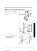
- Page 17: Mounting the bespoke panel (applicable models only) Open the door and fit the bespoke panel in the front bottom of the door. Make sure that the ribs of the panel fit into the corresponding holes (totaling 6) of the door. While holding the door and the bespoke panel with both hands, press the panel evenly from bottom to top to lock into the dishwasher.
- Page 18: Installation instructions for the Bespoke panel are provided. Ensure the Bespoke panel fits properly in the dishwasher. A gap of below 2 mm indicates proper installation. If the gap is 2 mm or more, remove and retry the installation. Unpack the caps and screws included in the product package. Tighten the screws on either side of the dishwasher. Check the gap between either side while tightening the screws. The Bespoke door may lean to either side if not properly adjusted. Press the top center of the Bespoke panel to secure it to the door. Follow the steps carefully for successful installation.
- Page 19: After inserting the panel, check it with bare eyes. If the panel is not correctly inserted, or the gaps are not even in all four corners, reinstall the panel. Remove the screws on both sides of the door. Then, put the suction cups on the panel, one in the top left area of the panel and the other in the top right. Pull up the handles of the suction cups to remove the panel, then install the panel again. Using the cups in the center area may bend the panel. Make sure to put the suction cups in the top left and top right areas of the panel. Then, pull up the handle just once for each. Make sure the door is secured and stable before using the suction cups.
- Page 20: Insert the caps on either side. Make sure the rib of the cap fits in the hole of the dishwasher in the right direction. This is the completion of mounting the Bespoke panel. Any third-party panel other than Samsung’s Bespoke panel is not allowed for attachment. The customer is responsible for any problem resulting from such a third-party panel.
- Page 21: Preparing the dishwasher Attach the protective sticker to prevent damage. Before putting the protective sticker, clean the counter top. The length of the protective sticker is 26 inches (660 mm). Ensure that the circuit breaker and water supply valve are turned off. Before moving or laying down the dishwasher, adjust the height of the legs. This prevents the legs from breaking. Level the dishwasher by adjusting the height of the legs after placement.
- Page 22: Installation Insert the 3/4 90 degree fitting into the inlet valve. Tighten until the 3/4 fitting is tight. Detach the Velcro strips that secure the drain hose to the back of the dishwasher. Roll out the hose and ensure there are no kinks. Remove the junction box cover located at the bottom front right of the dishwasher. Install the strain relief and keep the junction box cover for later use. Attach the two installation brackets supplied with the dishwasher if the countertop is suitable. Secure the drain hose into the drain hose bracket if it needs to go to the right of the dishwasher. The drain hose bracket can be adjusted in three positions. To adjust the height of the drain hose bracket, squeeze the bracket and turn it to the left.
- Page 23: Do not overtighten the 90° fitting. Doing so may damage the water inlet valve and cause a water leak.
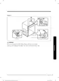
- Page 24: Installation Placing the dishwasher and connecting the hot water supply line Adjust the three leveling legs at the bottom of the dishwasher after measuring the height of the cabinet opening from under the countertop to the floor. Locate the hot water supply line and the power cable. Place the dishwasher so that the hot water supply line is in the left side and the power cable is in the right channel of the base of the dishwasher. Pull the drain hose through the hole in the sink cabinet side wall. Keep it free of kinks. Make sure the hot water supply line is not twisted, and then connect the hot water supply line to the fitting joint. Slide the dishwasher carefully into the installation space. Do not place the dishwasher on the water supply line, drain hose, or power cable. Also, make sure they are not folded or twisted. Wrap Teflon tape around every connection to prevent water leaks. Make sure both side gaskets are 13/16 to 1 (20-25 mm) backward from the front end of the kitchen cabinet.
- Page 25: Caution Do not overtighten the 90° fitting. Doing so may damage the water inlet valve and cause a water leak. Make sure the dishwasher is positioned to the center.
- Page 26: Installation Leveling the dishwasher Open the door and place the level against the top of the tub on the inside and check if the dishwasher is level. If it is not level, rotate the leveling legs at the bottom front of the dishwasher until the dishwasher is level. Use the level to check if the dishwasher is level front to back. If the dishwasher is not level front to back, adjust the height of the rear leg until the dishwasher is level. To prevent leaks from the door, make sure that the front of the dishwasher is not lower than the back. Open the door of the dishwasher and check if both the tub and door clearances are correct. If not, rotate the leveling legs on the bottom front of the dishwasher. You can also check this by placing a level against an inside front vertical surface of the tub.
- Page 27: If the leveling legs are rotated to the left (clockwise), they are loosened and the front of the dishwasher is raised. If they are rotated to the right (counter clockwise), they are tightened and the front of the dishwasher is lowered. You can adjust the leveling legs by a max of 16/32. However, leveling up to the max height is not recommended. To adjust the height of a rear leg, turn the T20 Torx (at the front of the base) to the left to raise the back of the dishwasher using the proper tool (T20 Torx). Before you move the dishwasher for installation, make sure to adjust the height of the legs so the legs are as short as possible. This prevents the legs from breaking. Level the dishwasher by adjusting the height of the legs after you have the dishwasher in place. If the product is installed unleveled or with the leg missing, the door may not close completely, causing a leak of steam or water. When adjusting the height of the dishwasher, make sure the top gasket is inserted seamlessly underneath the top of the kitchen cabinet. Otherwise, it may increase noise when the dishwasher is operating.
- Page 28: Installation Securing the dishwasher You must secure the dishwasher to the countertop or cabinet side walls for additional stability and safety. To the countertop If the countertop is made of wood or the material will not be damaged by drilling, follow this. Put a large towel into the bottom of the dishwasher to prevent wood shavings or a dropped screw from falling into the sump. Insert the provided brackets into the top front holes of the dishwasher as shown. Pre-drill the overlapping holes of the brackets. Make sure the hole is smaller than the diameter of the screw. Tighten the provided screws. Assemble the provided plastic caps as shown. After installing the dishwasher inside the cabinet, check if the door opens and closes freely with no interruption with the cabinet. If the plastic caps are not assembled, water may leak and cause a fire or electric shock.
- Page 29: If the countertop is made of granite, marble, or any other material that can be damaged by drilling, follow these instructions. Put a large towel into the bottom of the dishwasher to prevent wood shavings or a dropped screw from falling into the sump. Insert the provided brackets into the side front holes of the dishwasher. If the brackets are too long, cut them down using pliers. Pre-drill one hole into both sides of the kitchen cabinet. Make sure the hole is smaller than the diameter of the screw. Tighten the provided screws. Assemble the provided plastic caps as shown. After installing the dishwasher inside the cabinet, check if the door opens and closes freely with no interruption with the cabinet. If the plastic caps are not assembled, water may leak and cause a fire or electric shock.
- Page 30: Installation Check the parts on the sink to which the drain hose will be connected. There are several ways to insert the drain hose into the drain hose connector of the sink. You must connect the drain hose in accordance with the water pipe installation regulations in your region.
- Page 31: With disposal Air gap Drain hose Hose clamp Disposal with an air gap Without an air gap Check the size of the sink’s drain hose connector. Slide a hose clamp over the end of the drain hose. You must use a hose clamp. Failure to do so may cause water leakage. To prevent backflow, secure the drain hose to the side or back wall of the kitchen cabinet.
- Page 32: Installation Take caution not to damage the drain hose when installing the dishwasher. To prevent leaks or drainage problems, ensure the drain hose is not damaged, kinked, or twisted. Do not cut the ribbed area of the drain hose to fit the size. Be careful when cutting off the end of the drain hose as there is a risk of injury. Check for any foreign items in the drain hose and remove them. Make sure the drain hose is not cut, torn, or broken by sharp edges. A damaged drain hose causes a leak. Make sure to remove the plug from the food disposal.
- Page 33: To prevent backflow for models without the air gap, secure the drain hose to the side wall of the kitchen cabinet using cable ties or other fixtures. Make sure the drain hose is high at least 10 inches from the sink connector. If necessary, cut off the dotted line of the drain hose to fit the size.
- Page 34: Installation Wiring connections Before connecting the power cable to the dishwasher, make sure the circuit breaker is off. Unfasten the screw on the left side of the junction box located at the front bottom right of the dishwasher, and then open the junction box cover. In the junction box, find the three power wires from the dishwasher including the grounding line. Pass the power cable through the strain relief, and then into the junction box. Connect the black wire of the dishwasher to the black wire of the power cable by inserting both into a wire nut. Recheck each wire to ensure it is connected correctly and securely. Arrange all the wires into the junction box, and then close the cover and fasten the screw. Make sure the wires are not pinched and sticking out of the junction box.
- Page 35: Electrical shock hazard: To avoid electrical shock, do not work on an energized circuit. Only qualified electricians should perform electrical work. Fire hazard: To avoid a fire hazard, make sure electrical work is properly installed. Recheck each wire to ensure it is connected correctly and securely. Each colored wire should be connected to the corresponding wire of the same color. The wire should not be twisted counterclockwise.
- Page 36: Installation Completing the installation Open the door and remove all foam, paper packaging, and unnecessary parts. Turn on the circuit breaker you turned off before you began the installation. Open the water supply valve to supply water to the dishwasher. Turn on the dishwasher, and then select and run a cycle. Make sure to check for water leakage on both ends of the water supply line and drain hose connector. Check if the dishwasher turns on properly and check also if there is any leak. If the leakage check code of “LC” appears on the window panel, press and hold the Start button for more than 3 seconds to start draining. Once the leak is stopped, lay down the dishwasher as shown, and wipe out moisture from the water leakage sensor. Plug in the dishwasher, open the water supply and start the Smart Install Cycle. The Smart Install Cycle will run for about 7 minutes.
- Page 37: If the “LC” information code continues to appear on the window panel, contact a local service center. Finally, attach the kick plate to the bottom of the dishwasher. While keeping the rubber skirt of the door taut, push the kick plate from the front of the rubber skirt inward underneath the door of the dishwasher. Make sure the gaskets of the kick plate are flush with the floor and side walls. Then, tighten the screws to fix the plate. Make sure the kick plate does not interfere with the dishwasher's door opening and closing. Try to open the door 90 degrees, and make sure the door fully opens without any noise.
- Page 38: Power supply: 120 V, 15 A, 60 Hz AC Water pressure: 20-120 psi (140-830 kPa) Dimensions (Width × Depth × Height): 23 7/8 x 25 x 33 7/8 in. (605 x 636 x 860 mm) Dimensions (Width × Depth × Height): 23 7/8 x 27 5/16 x 33 7/8 in. (605 x 693 x 860 mm) Minimum inlet water temperature: 120 °F (49 °C) Specifications are subject to change without notice for quality improvement purposes. The actual appearance of the dishwasher may differ from the illustrations in this manual.
- Page 39: Page 39
- Page 40: Page 40
- Page 41: Lavavajillas Manual de instalación Serie DW80BB70*, Serie DW80B70*, Serie DW80B60*
- Page 42: Instrucciones de seguridad importantes Antes de usar la lavavajillas Instalación Dimensiones del producto Dimensiones del gabinete Especificaciones Escanee el código QR para ver videos útiles de instalación.
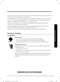
- Page 43: Instrucciones de seguridad A lo largo de este manual, encontrará notas de advertencia y precaución. Es su responsabilidad actuar con sentido común, precaución y cuidado cuando instale, realice el mantenimiento y ponga en funcionamiento la lavavajillas. Samsung no se responsabiliza por los daños ocasionados por un uso inadecuado. Significado de los íconos y señales de esta guía de instalación: ADVERTENCIA: Peligros o prácticas inseguras que pueden causar lesiones físicas graves o la muerte. PRECAUCIÓN: Peligros o prácticas inseguras que pueden causar lesiones físicas o daños materiales. Para reducir el riesgo de incendio, explosión, descargas eléctricas o lesiones físicas cuando usa esta lavavajillas, siga estas instrucciones de seguridad básicas. Estas señales de advertencia sirven para evitar que usted y otras personas sufran daños. Estas instrucciones de instalación están dirigidas a instaladores calificados. Después de leer esta sección, guárdela en un lugar seguro para consultas futuras.
- Page 44: Instrucciones de seguridad Lea todas las instrucciones antes de usar el electrodoméstico. Instale y guarde la lavavajillas en un lugar interior, no expuesto a los factores climáticos. No instale la lavavajillas cerca de componentes eléctricos. Mantenga la lavavajillas alejada de llamas abiertas. No instale la lavavajillas sobre una alfombra ya que existe peligro de incendio. No instale la lavavajillas en áreas donde el agua se congele. Esta lavavajillas debe conectarse a tierra correctamente. Todo el cableado y la conexión a tierra deben realizarse en conformidad con el código eléctrico vigente en la región. La lavavajillas es muy pesada. No intente mover o trasladar una lavavajillas usted solo. Si se daña el cable de alimentación, este deberá ser reemplazado por el fabricante o una persona calificada. No conecte otro electrodoméstico en el mismo tomacorriente donde está enchufada la lavavajillas.
- Page 45: Asegúrese de utilizar un conducto nuevo. Los conductos viejos pueden romperse y ocasionar daños materiales por pérdidas de agua. La lavavajillas debe estar conectada al suministro de agua caliente con una temperatura entre 120 ˚F (49 ˚C) y 149 °F (65 ˚C). Este rango de temperatura ofrece un mejor resultado en el lavado y un ciclo más corto. La temperatura no deberá exceder los 149 ˚F (65 ˚C) para no dañar la vajilla. Asegúrese de que el agua provista a la lavavajillas no se congele. Las lavavajillas residenciales certificadas no han sido diseñadas para los establecimientos alimentarios autorizados. No utilice la lavavajillas hasta que no esté correctamente instalada. No ejerza presión sobre la puerta de la lavavajillas cuando está abierta. Conecte a tierra la lavavajillas. El incumplimiento de estas instrucciones puede tener como resultado la muerte, incendios o descargas eléctricas.
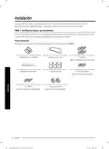
- Page 46: Instalación Asegúrese de que usted o su instalador siga estas instrucciones minuciosamente para que su nueva lavavajillas funcione adecuadamente y no existan riesgos de sufrir lesiones al lavar la vajilla. Verifique las piezas y las herramientas Antes de comenzar la instalación, prepare todas las herramientas y piezas necesarias requeridas para instalar la lavavajillas. Esto ahorrará tiempo y simplificará el proceso de instalación. Piezas necesarias Provistas con la lavavajillas. Verifique al desempacar la lavavajillas.
- Page 47: Cable de alimentación Conector de resorte Alivio de tensión Cinta aislante y cinta americana estándar Conducto de suministro de agua caliente Adaptador de 90° (de 3/4) Adaptador del tubo Conector de goma Abrazadera de manguera Para el conducto de suministro de agua caliente, se recomienda usar un tubo de cobre de diámetro exterior de un mínimo de 3/8 con adaptador de compresión. No utilice tubos de plástico. Se necesitan roscas para el tubo externo con un adaptador de 90° para tubo cónico de 3/4. Para el cable de alimentación, se recomienda utilizar un cable recubierto de 12-2 con conexión a tierra.
- Page 48: Instalación Herramientas requeridas Taladro eléctrico Llave ajustable Lentes de seguridad Alicate pelacable Guantes Pinza Linterna Alicate de corte Cinta métrica Lápiz Cúter Destornillador Phillips Destornillador plano Cortatubos Torx t20 Fresa para escariar Nivel Llave en forma de L para cabezas hexagonales Ventosa
- Page 49: Instalación nueva Si la instalación del lavavajillas es nueva, la mayor parte del trabajo debe realizarse antes de colocar el lavavajillas en su lugar. Reemplazo Si el lavavajillas reemplazara a un lavavajillas anterior, debe verificar que las conexiones existentes sean compatibles con el nuevo lavavajillas. Elección de la mejor ubicación para la lavavajillas Los siguientes criterios son importantes para garantizar la mejor ubicación de la lavavajillas: La ubicación debe tener un piso macizo que pueda soportar el peso del lavavajillas. La ubicación deberá ser cercana al fregadero con un acceso fácil al suministro de agua, desagüe y tomacorriente. Para que el desagüe funcione correctamente, la lavavajillas debe estar instalada a 9.8 pies (3 m) del fregadero. La ubicación debe permitirle colocar la vajilla dentro del lavavajillas con facilidad. La pared trasera no debe presentar obstrucciones. Asegúrese de que el gabinete de la lavavajillas esté asegurado al piso.
- Page 50: Instalación Si se trata de una instalación nueva, siga estos pasos: Utilizando una fresa para escariar de 2 1/2 pulgadas, realice una perforación en la pared del gabinete que soporta el fregadero. Si la base dentro del gabinete del fregadero se eleva sobre el piso de la cocina y es más alta que las conexiones en la lavavajillas, debe hacerse un agujero en la base dentro del gabinete y en el lateral del gabinete. Dependiendo del lugar donde se encuentre el tomacorriente, puede ser necesario realizar un agujero en el lado opuesto al gabinete. Asegúrese de que los bordes del orificio del gabinete estén lisos antes de insertar la manguera de drenaje. Un borde afilado del orificio del gabinete puede causar daños a la manguera de drenaje y provocar pérdidas.
- Page 51: Dimensiones del producto Vista frontal DW80BB7070**, DW80B7070** 237/8 (605 mm) DW80B7071**, DW80B6061** 237/8 (605 mm) Vista lateral DW80BB7070**, DW80B7070** DW80B7071** 275/16 (693 mm) Acomode el conducto, el cable de alimentación y la manguera de desagüe en el espacio detrás de la lavavajillas.
- Page 52: Instalación Dimensiones del gabinete Esta lavavajillas está diseñada para colocarse entre los lados y encima de un gabinete en una cocina residencial estándar. El gabinete para la instalación debe estar limpio y libre de obstrucciones. El gabinete debe tener por lo menos 24 pulgadas de ancho, 24 pulgadas de profundidad y 34 1/8 pulgadas de altura. Para que la puerta delantera de la lavavajillas esté nivelada con el borde delantero de la encimera, la encimera debe estar por lo menos a 25 pulgadas de profundidad.
- Page 53: Verifique los requisitos para el suministro de agua y precauciones. La presión del conducto de agua caliente debe estar entre 20 y 120 psi (140 y 830 kPa). Ajuste el calentador de agua para obtener una temperatura de agua entre 120 ˚F (49 ˚C) y 149 ˚F (65 ˚C). La lavavajillas debe estar conectada al suministro de agua caliente entre 120 ˚F (49 ˚C) y 149 °F (65 ˚C). Este rango de temperatura ofrece un mejor resultado en el lavado y un ciclo más corto. La temperatura no deberá exceder los 149 ˚F (65 ˚C) para no dañar la vajilla. Asegúrese de que la válvula del suministro de agua esté cerrada antes de conectar el conducto de agua caliente al lavavajillas. Selle las conexiones del conducto de agua caliente con cinta teflón o pasta de sellado para detener cualquier pérdida de agua. La manguera de desagüe conectada al lavavajillas debe pasar por el orificio de la pared lateral a fin de conectarla a la salida del desagüe del fregadero. Asegúrese de que no haya nada en la manguera de desagüe y tenga cuidado de no dañarla durante el proceso de instalación.
- Page 54: Instalación Verifique los requisitos eléctricos y advertencias. Los requisitos eléctricos para la lavavajillas son los siguientes. En los Estados Unidos, instalar de conformidad con el Código Eléctrico Nacional/códigos estatales y municipales y/o códigos locales. En Canadá, instalar de conformidad con el Código Eléctrico Canadiense C22.1-última edición/códigos provinciales y municipales y/o códigos locales. Utilice un cable de cobre recubierto enfundado no metálico con una conexión a tierra que cumpla con los requisitos de cableado de los códigos y ordenanzas locales. Utilice el método del aliviador de tensión provisto con la caja de conexiones de cableado o instale una abrazadera de conector incluida en U.L./certificada por CSA en la caja de conexión de cableado.
- Page 55: Desempacar e inspeccionar el lavavajillas. Desempaque la lavavajillas en una zona libre de obstrucciones. Conserve todos los materiales del empaque hasta que la lavavajillas esté completamente instalada. Ubique el lado derecho de la caja con las flechas superiores señalando hacia arriba. Desate o corte las correas que aseguran la caja. Levante la lavavajillas de la bandeja de la caja y colóquela sobre el piso. Siempre levante la lavavajillas para moverla. No retire, bajo ninguna circunstancia, el aislante de protección que rodea el exterior de la cuba de la lavavajillas. Localice y separe la placa de protección de la lavavajillas. También se encuentra material de empaque dentro de la lavavajillas.
- Page 56: Instalación Verifique el montaje de la base de plástico para asegurarse que esté intacto. Verifique los soportes de la lavavajillas para asegurarse de que estén en su lugar y que puedan ajustarse con el fin de nivelar y asegurar la lavavajillas. Verifique todas las piezas visibles en la parte inferior de la lavavajillas para asegurar que estén intactas y seguras. Verifique la traba de la puerta, el funcionamiento de las bisagras, y confirme que la puerta esté correctamente asegurada a la lavavajillas. Verifique la conexión de agua caliente en el lado izquierdo trasero de la base de la lavavajillas. Revise que la lavavajillas y todos los accesorios estén incluidos en la caja para asegurarse de que estos montajes no estén dañados. Verifique que la manguera de desagüe no tenga perforaciones o deformidades que ocasionen la filtración de agua durante el desagüe. Confirme que la tapa de la caja de conexiones esté asegurada a la caja de conexiones en el lado derecho delantero de la base de la lavavajillas. Confirme que la caja eléctrica no se haya dañado durante el transporte y que esté asegurada a la base de la lavavajillas. Confirme que no haya abolladuras o raspones en la parte del frente de la lavavajillas.
- Page 57: Montaje del panel Bespoke (solo modelos aplicables) Abra la puerta y coloque el panel Bespoke en la parte inferior frontal de la puerta. Asegúrese de que las nervaduras del panel encajen en los orificios correspondientes (en total 6) de la puerta. Mientras sujeta la puerta y el panel Bespoke con ambas manos, presione el panel de manera uniforme de abajo hacia arriba para que calce en la lavavajillas.
- Page 58: Instalación Cuando ambos lados del panel encajen en su lugar, presione el centro superior del panel Bespoke para asegurarlo a la parte superior de la puerta. Asegúrese de que el panel Bespoke encaje bien en la lavavajillas. Si el espacio entre la lavavajillas y el panel Bespoke es inferior a 2 mm, la instalación es correcta. Para 2 mm o más, quite el panel Bespoke y vuelva a intentarlo. Desembale las tapas y los tornillos (dos para cada uno) incluidos en el paquete del producto. Apriete los tornillos a cada lado de la lavavajillas. Cuando ajuste el tornillo en cualquiera de los lados, asegúrese de verificar el espacio entre los lados, ya que la puerta de Bespoke podría inclinarse en cualquier dirección.
- Page 59: Nota Después de insertar el panel, revíselo a simple vista. Si el panel no está bien insertado o los espacios no son uniformes en las cuatro esquinas, vuelva a instalar el panel. Reinstalación Retire los tornillos a ambos lados de la puerta. Coloque las ventosas en el panel, una en la parte superior izquierda y la otra en la parte superior derecha. Jale hacia arriba las manijas de las ventosas para quitar el panel, luego vuelva a instalarlo. Precaución Si usa las ventosas en el área central, puede doblar el panel. Asegúrese de colocar las ventosas en las áreas superior izquierda y superior derecha del panel. Asegúrese de que la puerta esté bien fijada y estable antes de usar las ventosas.
- Page 60: Instalación Inserte las tapas a cada lado. Asegúrese de que la nervadura de la tapa encaje en el orificio de la lavavajillas en la dirección correcta. Así se completa el montaje del panel Bespoke. No se permite la instalación de ningún panel de terceros que no sea el panel Bespoke de Samsung. El cliente es responsable de cualquier problema que surja de dicho panel de terceros.
- Page 61: Preparación del lavavajillas Coloque el autoadhesivo protector en la parte inferior de la encimera. Antes de aplicar el autoadhesivo protector, limpie la encimera. El autoadhesivo protector mide 26 pulgadas (660 mm) de largo. Asegúrese que el disyuntor y la válvula del suministro de agua estén desactivados. Antes de mover o apoyar la lavavajillas, ajuste la altura de las patas. Esto evita que las patas se rompan. Nivele la lavavajillas ajustando la altura de las patas luego de colocar la máquina en su lugar.
- Page 62: Instalación Luego, inserte el adaptador de 3/4 90 grados en la válvula de entrada. Ajuste hasta que el adaptador de 3/4 quede ajustado. No lo ajuste demasiado. Separe las tiras de velcro que fijan la manguera de desagüe a la parte trasera de la lavavajillas. Asegúrese de que no haya dobleces y que la manguera no está inclinada en ninguno de los ángulos extremos que podrían obstruir el flujo del agua. Con un destornillador quite la tapa de la caja de las conexiones ubicada en la parte inferior derecha del frente de la lavavajillas y luego instale el alivio de tensión. Asegúrese de conservar la tapa de la caja de conexiones que quitó. Si la encimera es de madera o si se trata de un material que no se daña al perforarlo, coloque las dos ménsulas de instalación que fueron provistas con la lavavajillas utilizando los tornillos provistos. Se utilizarán en el paso 10, fijación de la lavavajillas. Si la manguera de desagüe debe ir a la derecha de la lavavajillas, asegúrela en el soporte de la manguera de desagüe montado en la base. El soporte de la manguera de desagüe se puede ajustar en 3 posiciones.
- Page 63: Adap tador de 90°. No ajuste demasiado el adaptador de 90˚. Si lo hiciera, podría dañar la válvula de entrada de agua y ocasionar una pérdida de agua.
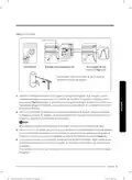
- Page 64: Instalación Colocación del lavavajillas y conexión del conducto del suministro de agua caliente Regule las tres patas niveladoras en la parte inferior de la lavavajillas después de medir la altura de la abertura del gabinete. Ubique el conducto del agua caliente y el cable de alimentación. Coloque la lavavajillas de manera tal que el conducto del agua caliente esté en el lado izquierdo y el cable de alimentación en el canal derecho. Saque la manguera de desagüe por el orificio en la pared lateral del gabinete del fregadero. Asegúrese de que el conducto del agua caliente no esté torcido y luego conéctelo a la junta del adaptador. Deslice la lavavajillas con cuidado hacia su espacio de instalación. No coloque el lavavajillas sobre el conducto, la manguera de desagüe o el cable de alimentación. Asegúrese de que el conducto de agua caliente esté bien conectado y envuelva con cinta Teflón todas las conexiones. Asegúrese de que los burletes laterales estén perfectamente insertados para evitar ruido durante el funcionamiento.
- Page 65: Burlete lateral Manguera de desagüe Conducto de suministro de agua caliente Válvula de entrada Gancho incorporado Conducto de suministro de agua caliente Codo (3/4 (9.5 mm)) Precaución No ajuste demasiado el adaptador de 90˚. Asegúrese de que la lavavajillas esté ubicada en el centro.
- Page 66: Instalación Nivelación del lavavajillas Abra la puerta y coloque el nivel contra la parte superior de la cuba desde adentro y verifique si la lavavajillas está nivelada. Gire las patas niveladoras en la parte inferior delantera de la lavavajillas hasta que quede nivelada. Utilice el nivel para verificar si la lavavajillas está nivelada de adelante hacia atrás. Ajuste la altura de la pata trasera hasta que la lavavajillas esté nivelada. Para evitar pérdidas de la puerta, asegúrese de que la parte de enfrente de la lavavajillas no esté más baja que la parte de atrás. Abra la puerta de la lavavajillas y verifique que tanto la separación de la cuba como la de la puerta sean correctas.
- Page 67: Si gira las patas niveladoras hacia la izquierda, estas se alejan y la parte delantera del lavavajillas se levanta. Si las gira hacia la derecha, se ajustan y la parte delantera del lavavajillas baja. Puede regular las patas niveladoras un máximo de 16/32. No obstante, no es recomendable ajustarlas a esta altura máxima. Para ajustar la altura de una pata trasera, gire el T20 Torx hacia la izquierda para levantar la parte posterior del lavavajillas utilizando la herramienta apropiada. Antes de mover la lavavajillas para su instalación, debe asegurarse de ajustar la altura de las patas de modo que estas sean lo más cortas posible. Si instala el producto desnivelado o sin una pata, la puerta puede que no cierre completamente, lo que daría lugar a fugas de vapor o de agua. Cuando ajuste la altura de la lavavajillas, asegúrese de que el burlete superior esté perfectamente insertado debajo de la parte superior del gabinete de la cocina.
- Page 68: Instalación Asegurar la lavavajillas La lavavajillas debe asegurarse a la encimera o a las paredes laterales para mayor estabilidad y seguridad. Si la encimera está hecha de madera de un material que no se daña por la perforación, siga las siguientes instrucciones. Coloque una toalla grande en la parte inferior de la lavavajillas para evitar que caigan restos de madera o un tornillo dentro del sumidero. Inserte las ménsulas que se proveen en los orificios de la parte superior delantera de la lavavajillas. Perfore los orificios superpuestos de los soportes. Asegúrese de que el orificio sea más pequeño que el diámetro del tornillo. Ajuste los tornillos provistos. Ensamble las tapas plásticas provistas como se ilustra. Asegúrese de que la puerta se abra y se cierre libremente sin que interfiera el gabinete. Si no se ensamblan las tapas plásticas, puede haber una pérdida de agua que cause un incendio o descarga eléctrica.
- Page 69: Hacia los laterales Si la encimera está hecha de granito, mármol o cualquier otro material que no se daña por la perforación, siga las siguientes instrucciones. Coloque una toalla grande en la parte inferior de la lavavajillas para evitar que caigan restos de madera o un tornillo dentro del sumidero. Inserte las ménsulas que se proveen en los orificios de la parte lateral delantera de la lavavajillas. Si las ménsulas son demasiado largas, córtelas utilizando un alicate de corte. Perfore un orificio en ambos lados del gabinete de la cocina. Asegúrese de que el orificio sea más pequeño que el diámetro del tornillo. Ajuste los tornillos provistos. Ensamble las tapas plásticas provistas como se ilustra. Luego de instalar la lavavajillas en el gabinete, asegúrese de que la puerta se abra y se cierre libremente sin que interfiera el gabinete. Si no se ensamblan las tapas plásticas, puede haber una pérdida de agua que cause un incendio o descarga eléctrica.
- Page 70: Instalación Verifique las piezas del fregadero a las cuales se conectará la manguera de desagüe. Hay muchas maneras de insertar la manguera de desagüe en el conector de la manguera de desagüe del fregadero. Debe conectar la salida del desagüe conforme a las reglamentaciones de instalación de tuberías de agua de su región. Caso 1. Sin triturador Con un espacio de aire/sin triturador Sin un espacio de aire
- Page 71: Caso 2. Con triturador Verifique el tamaño del conector de la manguera de desagüe del fregadero. Quite el tapón ciego del triturador de basura antes de conectar la manguera de desagüe. Deslice una abrazadera de manguera en el extremo de la manguera de desagüe. Asegúrese de que la manguera de desagüe se encuentre a una altura de al menos 10 pulgadas del conector del fregadero. Cuando realice un agujero en la pared del gabinete para la manguera de desagüe, tenga cuidado de que los bordes filosos del orificio no dañen la manguera. Si no utiliza una abrazadera de manguera, es posible que haya pérdidas de agua. Asegure la manguera de desagüe en la pared lateral o trasera del gabinete de la cocina. Si las paredes son de madera, lije los bordes para suavizarlos. Si las paredes son de metal, use cinta aislante o cinta americana para cubrir los bordes filosos. Conecte la manguera de desagüe al conector del fregadero.
- Page 72: Instalación Tenga cuidado de no dañar la manguera de desagüe al instalar la lavavajillas en el piso, la pared o el gabinete. Para evitar pérdidas o problemas de drenaje, asegúrese de que la manguera de desagüe no esté dañada, retorcida o enredada. No corte la zona con ranuras de la manguera de desagüe para que se adapte al tamaño. Tenga cuidado al cortar el extremo de la manguera de desagüe ya que podría lastimarse. Limpie el área de conexión del desagüe del fregadero para evitar que la manguera se dañe. Verifique que no haya objetos extraños en la manguera de desagüe y quítelos. Cuando acomode la manguera de desagüe, asegúrese de que no tenga cortes causados por los bordes afilados del piso, el producto o el gabinete. Una manguera dañada causa pérdidas. Asegúrese de remover el tapón de la parte de eliminación de alimentos.
- Page 73: Para evitar el flujo de retorno en los modelos sin espacio de aire, asegure la manguera de desagüe en la pared lateral del gabinete de la cocina mediante sujetacables o con otras monturas. Asegúrese de que la manguera de desagüe se encuentre a una altura de al menos 10 pulgadas del conector del fregadero.
- Page 74: Instalación Conexiones del cableado Antes de conectar el cable de alimentación a la lavavajillas, asegúrese de desactivar el disyuntor. Ajuste el tornillo en el lado izquierdo de la caja de conexiones ubicada en la parte inferior derecha de la lavavajillas y, luego, abra la tapa de la caja. En la caja de conexiones, encontrará los tres cables de la lavavajillas, incluido el cable de conexión a tierra. Pase el cable de alimentación por el alivio de tensión y, luego, dentro de la caja de conexiones. Conecte el cable negro de la lavavajillas al cable negro del cable de alimentación. Revise nuevamente cada uno de los cables para asegurarse de que estén bien conectados y de una manera segura. Coloque todos los cables en la caja de conexiones y, luego, cierre la tapa y apriete el tornillo. Asegúrese de que los cables no queden atrapados ni sobresalgan de la caja de conexiones.
- Page 75: Riesgo de descarga eléctrica Para evitar descargas eléctricas, no manipule un circuito energizado. Solo los técnicos de servicio calificados pueden realizar conexiones eléctricas. No intente manipular el circuito de suministro eléctrico de la lavavajillas hasta que no esté seguro de que está desenergizado. Riesgo de incendio Para evitar el riesgo de incendio, asegúrese de que la instalación eléctrica sea correcta. Revise nuevamente cada uno de los cables para asegurarse de que estén bien conectados y de una manera segura. Cada cable de un color debe conectarse con el cable del mismo color correspondiente. El cable no debe torcerse en sentido antihorario.
- Page 76: Instalación Finalización de la instalación Abra la puerta y quite todas las piezas innecesarias, goma espuma y empaque de papel. Active el disyuntor desactivado antes de comenzar la instalación. Abra la válvula del suministro de agua para suministrar agua a la lavavajillas. Verifique las filtraciones de agua en ambos extremos del conducto de agua y en el conector de la manguera de desagüe. Si aparece el código de verificación de pérdidas “LC” en el panel, mantenga presionado el botón Start durante más de 3 segundos para comenzar el drenaje. Revise si hay pérdida en la válvula de entrada. Una vez contenida la fuga, apoye la lavavajillas como se muestra y seque la humedad del sensor de pérdidas de agua. Enchufe la lavavajillas, abra el suministro de agua e inicie el ciclo de instalación inteligente. El ciclo de Instalación inteligente se ejecutará durante 7 minutos aproximadamente.
- Page 77: Si el código de información “LC” continúa apareciendo en el panel, comuníquese con un centro de servicio técnico local. Coloque la placa de protección en la parte inferior de la lavavajillas. Asegúrese de que los burletes de la placa de protección estén nivelados a la perfección con el piso y las paredes laterales. Ajuste los tornillos para fijar la placa. Asegúrese de que la placa de protección no interfiera con la apertura y cierre de la puerta de la lavavajillas. Intente abrir la puerta 90 grados y asegúrese de que se pueda abrir completamente sin hacer ruido.
- Page 78: Especificaciones Suministro eléctrico: 120 V, 15 A, 60 Hz CA Presión de agua: 20 - 120 psi (140 - 830 kPa) Dimensiones (Ancho × Profundidad × Altura): 23 7/8 x 25 x 33 7/8 pulg. (605 x 636 x 860 mm) Temperatura mínima del agua en la entrada: 120 °F (49 °C) Las especificaciones están sujetas a cambios sin previo aviso a los efectos de las mejoras de calidad. La apariencia real de la lavavajillas puede diferir de las ilustraciones de este manual.
- Page 79: Page 79
- Page 80: Page 80

FISHER and PAYKEL DD24DTX6I1 Tall Dishwasher

FISHER AND PAYKEL DD24DTX6I1 Dishwasher

FISHER PAYKEL DD60D4ZB9 Double Dishwasher

Miele 12 668 930 Dishwasher

IKEA SODERBODA Integrated Dishwasher

SIEMENS SX95Z802CE XXL iQ500 Dishwasher

SHARP QW-NA25GU44BS-DE Undercounter Dishwasher
FISHER PAYKEL DW60U2I1 Dishwasher

BOSCH 9001164801 Dishwasher

FISHER AND PAYKEL DD24DTX6HI1 Dishwasher