
beko DDS25842X Dishwasher


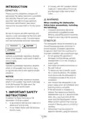












Dishwasher
Installation Manual
DIS25842
DDS25842X
USA
15 8018 0100_45BEKO_USA/ 08-11-23.(17:57)

| General | Details |
|---|---|
| Name | beko DDS25842X Dishwasher |
| Make | Beko |
| Language | English |
| Filetype | PDF (Download) |
| File size | 5.78 MB |
 (1 votes, average: 5.00 out of 5)
 Loading...

beko DUT25401WHW Front Pocket Handle Dishwasher

beko BDIN38522Q Dishwasher

beko BDFN26450A Dishwasher

beko BDFS26046XQ Dishwasher

beko BDFN26521XQ Dishwasher

NMG0724BEKODI Dishwasher

beko 943711 Dishwasher

beko DIN15210 Full-Size Dishwasher

beko 57 6190 0000 Tall Tub Dishwasher

beko BDIN38650C Dishwasher

beko DDS25842X Dishwasher Overview
Summary of Contents
- Page 1: Dishwasher installation manual. Model numbers: DIS25842 and DDS25842X. Intended for the USA market. Document version date: 08-11-23.
- Page 2: To prevent accidents, which could cause serious injury or death, as well as machine damage, read these instructions before installation and/or use. CONTENTS INTRODUCTION IMPORTANT SAFETY INSTRUCTIONS INSPECT THE DISHWASHER TOOLS WHICH MAY BE NEEDED MATERIALS WHICH MAY BE NEEDED MATERIALS SUPPLIED DISHWASHER SPECIFICATIONS TECHNICAL FEATURES PREPARATIONS LEVELING INSTALLING THE SIDE PLUGS CONNECTING THE WATER LINE PREPARING THE CUSTOM PANEL SECURING TO THE CABINETRY CONNECTING THE DRAIN LINE FINISHING STEPS INSTALLER CHECKLIST SELF HELP HINTS
- Page 3: In Canada, follow the Canadian Electric Code C22.1-latest edition and local codes for installation. Please read this installation manual and safety instructions completely to ensure optimum dishwasher performance. Installation and repair should be performed by a qualified installer to avoid danger and warranty voiding. The dishwasher should be installed by an insured licensed plumber, contractor, or trained installer. Do not operate the appliance if damaged, malfunctioning, partially disassembled, or if it has missing or broken parts. To reduce the risk of electric shock, fire, or injury, ensure the dishwasher is completely enclosed during installation. Only connect the dishwasher to the power supply when all installation and plumbing work is complete. If installed in freezing temperatures, drain all water from the dishwasher’s interior to prevent warranty voiding. Indicates a potentially hazardous situation which, if not avoided, may result in injury or damage. In addition to these instructions, the dishwasher shall be installed in accordance with all local codes or the National Electric Code in the absence of local codes.
- Page 4: Connect to a properly rated, protected and sized power supply circuit to avoid electrical overload. The dishwasher is designed for an electrical supply of 120 V, 60 Hz, AC, connected to a dishwasher-dedicated, properly grounded electrical circuit with a fuse or breakers rated for 15 amperes. Electrical supply conductors shall be a minimum of # 16 AWG copper wire rated at 75 °C or higher. Consult a qualified electrician if in doubt. Do not use any extension cord or portable outlet device to connect the dishwasher to a power supply. Ensure that any plastic wrappings, bags, small pieces etc. are disposed of safely and kept out of the reach of children. After unpacking the dishwasher and prior to installation, thoroughly inspect the dishwasher for possible freight or cosmetic damage. Cosmetic defects must be reported within 10 days of installation. Remove the door to the washing compartment when removing an old dishwasher from service or discarding it. The dishwasher drain hose must be installed with a drain loop at least 28” off the cabinet floor; otherwise the dishwasher may not drain properly.
- Page 5: Tools which may be needed include wire cutter, pipe wrench, drill, wire stripper, Phillips screwdriver, scissors, hole saw, hammer, Torx screwdriver, Scot screwdriver, brush, tape measure, adjustable wrench, level, and pencil. Materials which may be needed include hot water supply line, 3/4” FHT x 3/8” MHT connector, UL listed conduit connector or strain relief, Teflon tape, shut-off valve and fittings, silicone, glue, and dishwasher discharge hose adaptor. Additional materials may be required to comply with local codes.
- Page 6: Materials supplied include caps and screws, kick plate brackets, and various parts for the dishwasher. Parts for the dishwasher come in several plastic bags, and it's important to check these bags to ensure all parts are included. The manual bag contains essential documents such as the user manual and installation manual. The dishwasher parts bag includes components necessary for installation, which may vary depending on the model. Parts attached to the rear of the dishwasher include screws, mounting brackets, and clamps. Side trim strips and toe kicks are also part of the supplied materials, with variations based on model specifications. A drilling template and steam protection foil are included for installation purposes. Ensure to verify the quantity and specifications of each part as listed. Installation kits may include additional components for models that accept custom panels. Check for compatibility and completeness of parts before proceeding with installation.
- Page 7: Dishwasher specifications include built-in and built-under dimensions. The minimum height for built-in models is 5.5 lbs (2.5 kg). The maximum weight for built-in models is 12.1 lbs (5.5 kg). Built-in dimensions are typically 24” (610 mm) wide. The minimum height for built-under models is 6 1/1” (18 mm). Built-under dimensions also measure 24” (610 mm) wide. The height for built-under models can reach up to 18” (460 mm). Specifications provide essential measurements for installation. Dimensions are crucial for ensuring proper fit in kitchen spaces. Weight limits are important for safe operation and installation.
- Page 8: Technical features include permissible water pressure of 4.35 - 145 psi and electrical connection specifications. The required circuit breaker is 15 A, dedicated, with a total power of 1400 W. Heater power is specified at 1100 W. Specifications and design may change without prior notice. The device corresponds to UL 749 Household Dishwasher directive. Foam rubber installation is recommended for improved soundproofing. Electrical preparation requires a 120 V, 60 Hz AC supply. The dishwasher must be connected to a dedicated, properly grounded electrical circuit. A fuse or breaker rated for 15 amperes is necessary.
- Page 9: Steam will form inside the dishwasher during operation. At the end of the cycle, when the dishwasher door is opened, it is required to use a steam protection foil to prevent any steam from collecting on the underside of the countertop. Before applying the steam protection foil to the underside of the countertop, clean the area with a damp cloth. Once the area dries, apply the steam protection foil. The steam protection foil will be applied at the location where the hot steam escapes when you first open the door. Steam protection foil must be applied where the steam escapes when the door is first opened. Failure to install the steam protection foil during installation can lead to damage to the cabinets and countertop.
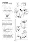
- Page 10: Leveling Adjusting height Make sure the counter height is taller than 3 7/16” (870 mm) to use the extra feet provided. If the height of the enclosure is 33 7/8” to 35 7/8” (861 mm - 911 mm) install the feet for both sides as shown in the figure. Adjust the front foot level by hand or slotted screwdriver to balance and raise the dishwasher to the enclosure height. Adjust the rear foot level with a screwdriver to balance and raise the dishwasher to the enclosure height. Make sure the dishwasher is plumb and can be placed under the counter with approximately 3/32” (2 mm) of clearance. Turning the screwdriver in the direction of the black arrows will raise the rear feet, causing the dishwasher to go down in the back. Turning the screwdriver in the direction of the white arrows will lower the rear feet, causing the dishwasher to go up in the back.
- Page 11: Installing the side plugs involves placing them on both sides of the machine and tightening by hand without using a screwdriver. When installing the side trim strips, ensure the correct side of the trim is facing forward. Remove the adhesive tape before placing the trim strips on the front edge of the side walls.
- Page 12: Preparation for installing mounting brackets Dishwasher must be secured to adjacent cabinetry or the countertop above using the mounting brackets provided. Failure to do this may cause damage to property or bodily injury. Place the two mounting brackets into the top corners of the dishwasher. Bend sides of mounting brackets as shown in the figure.
- Page 13: Connecting the water line Preparing the water connection Install an easily accessible shut-off valve in the water supply line. All solder connections must be made before the water line is connected to the dishwasher’s water inlet valve. Water can also be supplied to the dishwasher by using a flexible braided hose line. Check with your plumbing supply sources for the proper hose and elbow and necessary fittings for the water supply line. Installation should be performed by a qualified installer. If the dishwasher is installed in a location that experiences freezing temperatures, you must drain all the water from the dishwasher’s interior. Water supply may be connected to the dishwasher in one of two ways: with metal braided hose or with copper tubing.
- Page 14: Caution regarding hot water supply line: Use minimum 3/8” O.D. copper tubing or metal braided dishwasher supply line. Temperatures for soldering and sweating can damage the dishwasher’s water inlet valve; keep heat source at least 7 7/8” away. Avoid sharp bends in the water line that may restrict water flow. Use Teflon tape or pipe thread compound for sealing connections. Flush the copper water supply line with hot water before connecting to the dishwasher. After making connections, turn on the water supply to check for leaks. Before placing the machine in the cabinet, remove the hose holders from the back. If hose holders are not removed, the machine cannot be fully placed in the cabinet. Do not discard hose holders; they can be used to secure the hose to the cabinet or wall.
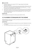
- Page 15: Now place the dishwasher into the opening and get ready to connect all hoses and electrical connections. Make sure all hoses are pulled through the side opening of the cabinet, no hoses are kinked and all slack is taken out as shown in the above figure.
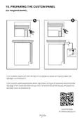
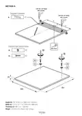
- Page 16: Preparing the custom panel for integrated models involves specific methods based on the panel's positioning. If the custom panel is flush with the top of the display, use Method A for template placement. If the custom panel extends above the display, measure down from the top edge to determine the placement for Method B. Video instructions are available via a scan code.
- Page 17: Method A Supplied template Custom door stud & screw Height: 26 to 28 11/32 (660 mm - 720 mm) Width: 17 3/8 to 17 5/8 (442 mm - 448 mm) Thickness: Min. 11/16 (18 mm) Weight: 5.5 lbs to 12.1 lbs (2.5 kg - 5.5 kg)
- Page 18: Method B Supplied template Custom door stud & screw Height: 26 to 28 11/32 (660 mm - 720 mm) Width: 17 3/8 to 17 5/8 (442 mm - 448 mm) Thickness: Min. 11/16 (18 mm) Weight: 5.5 lbs to 12.1 lbs (2.5 kg - 5.5 kg)
- Page 19: Installing the custom panel handle requires ensuring the screw is fully tightened. To prepare the product door, peel the protective cover off one side of the adhesive strip and apply it to the dishwasher door location.
- Page 20: Installing the custom panel involves removing the outer protective cover on both adhesive strips. The panel should be slid into the mounting studs located in the channels on each side of the door. Once positioned, hold the panel and squeeze the bottom to engage the adhesive strips for secure placement.
- Page 21: Securing the custom panel involves removing the plastic plugs located in the fifth screw position from the top on each side. Secure the custom panel to the product through hole 5 with the supplied screws on each side.
- Page 22: Securing to the cabinetry involves readjusting foot levels. Readjust the front foot levels with a slotted screwdriver or by hand to ensure the dishwasher is level and properly positioned under the countertop. Adjust the rear foot levels using a screwdriver to balance the dishwasher and achieve the required height with the supplied brackets. Attach the dishwasher underneath the counter using the four screws provided.
- Page 23: Attaching the corner brackets is essential for proper installation. Ensure the machine is level with the counter. The machine should not be ahead or behind the counter. For wooden counters, fix the mounting brackets on the right and left sides under the bench. For non-wooden benches, also fix the mounting brackets on the right and left sides under the bench. Avoid going through the top of the countertop or damaging granite.
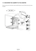
- Page 24: Securing the cabinet to the counter involves fixing the machine from the inside at four indicated points. Use the provided screws for this purpose.
- Page 25: Connecting the drain line involves specific connection information. The dimensions include 1/2 (20.9 mm) and 3/4 (26.4 mm) fittings. Minimum pressure is 0.05 MPa/0.5 Bar, and maximum pressure is 1 MPa/10 Bar. Various lengths are specified, including approximately 59 1/16” (1500 mm), 70 7/16” (1800 mm), and 78 3/4” (2000 mm). The minimum diameter required is 1” (25 mm).
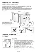
- Page 26: Drain hose connection Connect the drain hose to the drain plumbing. Use the supplied rubber connection hose and drain hose clamps to connect the dishwasher drain hose to the plumbing drain connection. Use the spring clamp to secure the rubber connection hose to the dishwasher drain hose. Use the screw clamp to secure the rubber connection hose to the plumbing drain connection. Note that the marks on the rubber connection hose should be on the drain hose side. Drain preparation The dishwasher drain hose may be connected to the drain plumbing in one of three ways. One of the drain connections shown in the illustrations must be used or the dishwasher will not operate properly. A hose that attaches to a sink spray can burst if it is installed on the same water line as the dishwasher. The total length of the drain hose is approximately 7 feet (1950mm).
- Page 27: The maximum length must not exceed approximately 13 feet (4000mm). You must add a loop at least 28” (710mm) above the floor of the cabinet and above the drain connection in the drain hose to prevent waste water from not draining properly. Check with local ordinance for type of air gap required. If the local ordinance requires an air gap. Be sure to remove the plug inside the connection point on the disposer before connecting the drain hose. Every disposal has a hook up for a dishwasher; consult your disposer manual for correct connection. Due to local building code requirements, some dishwasher installations require hooking up. Please use the connector piece provided with the machine with instructions illustrated.
- Page 28: Finishing steps involve installing the toe kick brackets. The toe kick can be adjusted to the height needed for your kitchen. There is a left and a right bracket for the installation. Adjust the toe kick brackets forward or backward to align with the kitchen toe kick. Place parts labelled “u” (left) and “uu” (right) into the specified channel. Fix the brackets in the direction indicated by the arrows in the installation guide. Measure the counter height to determine the appropriate parts to use. Different counter heights require different combinations of parts for installation. Follow the specific steps according to the dimensions of your counter height. Installations vary based on the height of the counter.
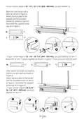
- Page 29: If your counter height is 32 1/4” - 33 1/16” (820 - 840 mm), use part labelled “w”. Bend the claw inward with pliers as shown in Figure A. Attach the kick plate to the bracket with the provided screws as shown in Figure B. Assemble the supplied screw cap as in Figure C. If your counter height is 33 1/8” - 34 1/4” (841 - 870 mm), use parts labelled “w” and “r”. Attach the “w” and “r” pieces together as shown in Figure A. Adjust the height you need by sliding it up and down as shown in Figure B. If your counter height is 34 5/16” - 36 1/4” (871 - 920 mm), use parts labelled “w” and “m”.
- Page 30: Attach the “w” and “m” pieces together as shown in Figure A. These parts can slide into each other. Adjust the height you need by sliding it up and down as shown in Figure B. Attach the kick plate to the bracket with the provided screws as shown in Figure C. Assemble the supplied screw cap as in Figure D. Check whether the bottom of the door hits the toe kick of the kitchen cabinet. If the door hits the toe kick, cut the necessary section out of the toe kick. Apply silicon or sealant to the cut edge of the kitchen cabinet toe kick or paint so it does not absorb moisture.
- Page 31: Electrical connection warnings include ensuring voltage and frequency match the household supply to prevent injury and damage. The dishwasher should only be connected to the mains after installation and plumbing work is complete. Extension cords or portable outlet devices should not be used for connection. The power-supply receptacle must be installed in a cabinet or wall adjacent to the undercounter space. The access hole for the supply cord must be smooth, rounded, and large enough for the attachment plug. Care should be taken to avoid damage to the power-supply cord during installation or removal. Grounding instructions state that the appliance must be grounded to reduce the risk of electric shock. It should be connected to a grounded outlet in accordance with local codes. Improper grounding can result in electric shock risks, and modifications to the plug should not be made. If the plug does not fit the outlet, a qualified electrician should install a proper outlet.
- Page 32: Installer checklist includes essential installation steps such as ensuring the drain hose is installed with a 28 high drain loop and that the drain plug is removed if connected to a garbage disposal. The spray arms should rotate freely, and the rinse cycle must be run to check functionality. It is normal to find some water in the drain filter area after the wash program. The dishwasher must be square, level, and securely fastened to the cabinetry. The door should open and close freely without obstruction from cabinetry or countertops. The inlet water supply must be turned on and checked for leaks, and the drain hose should be connected without kinks or obstructions. For self-help hints, if the screen does not come on, check the breaker and ensure the supply cord is plugged in. If no water is coming into the dishwasher, verify that the hot water shut-off is in the ON position. If water does not drain, ensure the drain hose is not kinked and remove the drain hose from the disposal, ensuring the plug is removed. If issues persist, contact the dealer for authorized service, as the manufacturer warranty does not cover installation or customer education service visits.

FISHER PAYKEL DD60SDFTB9 Tall Dishwasher

BOSCH SPV6HMX5MR Dishwasher

BOSCH SPI4HKS49E Dishwasher

BOSCH BSH21 Dishwasher

BOSCH SMS2HMW04E-30 Dishwasher

LG LD-2130-1-W-S-M-H Dishwasher

Whirlpool W11389327B Dishwasher

IKEA RENGOERA Dishwasher

BOSCH SMS4HCI19E Free Standing Dishwasher

AEG FSB42607Z Build In Dishwasher