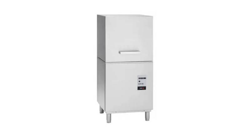
FAGOR AD-120CW Door Style Dishwasher


SERVICE MANUAL
**********
2013
DOOR STYLE DISHWASHER
DOOR STYLE DISHWASHER
Model: AD‐120CW

| General | Details |
|---|---|
| Name | FAGOR AD-120CW Door Style Dishwasher |
| Make | FAGOR |
| Language | English |
| Filetype | PDF (Download) |
| File size | 0.72 MB |


FAGOR 3LVF-421.1, 3LVF-421.1X Dishwasher

FAGOR 3LVF-423.1X Dishwasher
FAGOR AD-120CW Door Style Dishwasher Overview
Summary of Contents
- Page 1: Service manual for the 2013 door style dishwasher. Model: AD-120CW.
- Page 2: Specifications Installation Visual inspection Installation diagrams Water installation Electrical connection Operation Turning the machine on Troubleshooting Limited warranty
- Page 3: Specifications Model: AD-120 CW Performance/Capacities Racks per hr.: 60 Dishes per hr.: 1500 Wash Tank: 11.8 gal. / 44.6 liters Heating Elements Electric wash tank heater: 4.5 Kw Electric booster heater: 12 Kw Water Consumption / Requirements Gallons per hr. (Max. use): 48 gal. / 181 liters Gallons per cycles: .8 gal. / 3.02 liters Inlet temperature (Optimum): 140ºF / 60ºC Flow rinse pressure: 15 – 25 psi Operating Cycles Wash time (Seconds): 3 settings (35, 55, 100) Dwell (Seconds): 5 Rinse time (Seconds): 15 Total Time (Seconds): 3 settings (55, 75, 120) Dimensions / Shipping Width: 28 1/4” / 717 mm Depth: 32” / 813 mm Height: 62” / 1575 mm Max clearance for dishware: 16 ½” / 419 mm Rack: 20” x 20” / 500 mm x 500 mm Shipping weight: 330 lbs. / 150 kg Shipping volume (cu. ft.): 32 Temperatures Wash: 150ºF / 66ºC Rinse: 190ºF / 88ºC Technical Specifications Total Power Consumption Boiler Power Consumption Pump Power Consumption
- Page 4: Installation Before installing the unit, check the package and machine for damage. All machines have been tested, inspected, and packed at the factory and are expected to arrive in new, undamaged condition. Visually inspect the exterior of the package. Any damage should be noted and reported to the delivering carrier immediately. If damaged, open and inspect the contents with the carrier. In the event of concealed damage, notify the carrier and request an inspection. Contact the dealer through which you purchased the unit. Installation diagrams include water inlet, drain hose, electrical, terminal block, vacuum breaker, and pressure gauge.
- Page 5: The data plate is located on one side of the machine. Under no circumstances should the data plate be removed from the unit. The data plate is essential to identify the particular features of your machine. It is recommended that, in the event the data plate is removed, you copy down the essential information in this manual for reference before installation. Any transformations or changes made on the machines during installation should be reflected on the data plate. Leveling and adjusting the height of the appliance is done by turning the leveling stands to the desired height. Ensure that the unit is level before making any connections.
- Page 6: Water installation is carried out as shown in figures 3 and 4. The hot water line to the dishwasher must provide between 25 ±5 psi of water pressure. The hot water heater should be set to deliver ≥ 140°F (not lower than 120°F) water temperature to the dishwasher for best results. Use ¾” copper tubing inlet line. Caution: Do not confuse static pressure with flow pressure. Static pressure is the line pressure in a “no flow” condition. Flow pressure is the pressure in the fill line when the solenoid valve is opened during the cycle. The display of the pressure gauge shall be clearly visible to the operator of the machine. The gauge shall have increments of 1 psi (7 kpa) or smaller and shall be accurate to ±2 psi (±14 kpa) in the 20 psi (103-172 kpa) ranges. If the water pressure is less than 20 psi (1.4 kg/cm²), installation of a water pump is required. In areas where the pressure fluctuates or is greater than the recommended pressure, it is suggested that a water pressure regulator be installed.
- Page 7: Requested quality of the water includes hardness, conductivity, pH, chloride concentration, chlorine levels, and impurities. It is necessary to remove all foreign debris from the water line prior to connecting to the machine. Use only the supplied hoses at the water connections to avoid damage to the solenoid valve threads. For hard water supplies with a hardness over 2 grains or 10ºF and pH beyond the range of 7.0 – 8.5, a water conditioner must be installed. Check for any leaks after turning on the water supply and repair as required before placing the machine in operation. Water drainage installation requires attaching the drain hose and affixing a siphon pipe to prevent odors. All piping from the machine to the drain must be a minimum of 1-1/2” I.P.S. There should be an air gap between the machine drain line and the drain for proper drainage. For natural overflow efficiency, use a floor drain. Refer to the provided figure for the drain hose and components layout.
- Page 8: Electrical connection instructions require removing the front panel to access the electrical connection strip. Wires should be connected as shown in the provided figure, ensuring the power cord is inserted through the cord holder with enough length left. Connections must be tightened, and at least 39 inches of the power cord should be left free for cleaning purposes. A circuit breaker must be installed according to consumption guidelines and the data plate. The machine must be grounded for safety. Wiring schematics for both 1-phase and 3-phase connections are provided. Wire bundle 1 is identified as a thicker wire with a blue wire incorporated. A warning about electrical shock hazards emphasizes the need for a qualified electrician to ensure compliance with electrical codes. The customer is responsible for ensuring the electrical installation is adequate and conforms to the National Electrical Code and local ordinances. For customer service, contact information is provided.
- Page 9: Installation checklist Check off the following items as they are completed before proceeding to operate or service the dishwasher. Has the dishwasher been properly leveled? Has the service voltage been checked to ensure that it meets the requirements listed on the dishwasher specifications? Has the dishwasher been properly grounded? Are the electrical connections and plumbing pipes tightened to proper torque levels? Flush water supply line before opening water valve. Is the incoming water supply at 20-25 psi? Is the hot water supply at the optimum temperature (140ºF)? Has the drain plumbing been installed according to the instructions in this manual? Is the detergent for commercial dishwashers? In order to validate your warranty, this checklist must be returned along with the product registration card.
- Page 10: Turning the machine on requires pressing and holding the power button for five seconds. The machine will start filling up with water once powered on. After filling, the machine heats the rinse and wash tanks. The machine is ready to wash when the rinse thermometer indicates 180°F and the tank thermometer indicates 160°F. It is the user’s responsibility to wait for the minimum temperatures before starting the wash. The incoming water temperature should be higher than 120°F for optimal performance. There are three washing cycles available: P1, P2, and P3, lasting 60, 90, and 180 seconds respectively. LED indicators show the machine's operation status based on the selected program. Starting the dishwasher before the booster heater reaches 180°F will result in an extended wash cycle.
- Page 11: Draining must occur every day and after each meal rush in high applications. Set selector switch to the “0” setting (OFF). Raise hood and remove overflow tube to drain the unit. Do not lose O’ring. Remove the rack guide, bulk and long scrap baskets, and filter for cleaning. Wipe clean and dry the machine if the day is completed. Use soap and water for cleaning purposes, not abrasive detergents. Replace all components back into position. Clean washing and rinsing arms and nozzles periodically. The machine should not be left on overnight to avoid overheating and damage to internal parts.
- Page 12: Detergent control requires the use of commercial grade, high temperature, low suds liquid detergent. All machines come equipped with an internal detergent and rinse dispenser. Place the tube marked Detergent inside the detergent container. The tube with a blue stripe should be placed inside the rinse container. Tubes are clear to show that chemicals are being dispensed. You can control the amount of chemical being dispensed by adjusting the detergent dispenser. Verify all connections to the dispenser are hand-tight to prevent leaks. Control and maintain the level of detergent and rinse aid in the tanks. If installing a non-Fagor detergent and rinse pump, a form must be filled out prior to installation. The detergent pump and rinse dispensing pump will only work during the fill and rinse process.
- Page 13: Installation of external chemical pumps If you require the installation of a non Fagor detergent and rinse pump, a form must be filled out prior to installation by your installer. Failure to do so will void your warranty. This form can be located inside your dishwasher. Dishwasher already incorporates a terminal block where you can connect an external chemical pump. Green and violet are the connections for detergent. Green and white are the connections for rinse. Place external detergent injector at the back side of the machine above the stainless steel scrap filters. If a pH sensor or similar is required, this can be installed between washing pumps pipes. It is recommended to disconnect the detergent pump that comes with the machine.
- Page 14: Preparing the ware Pre-scrap and rinse all racks prior to placing them in the dishwasher to remove large food particles. Wash glassware first. Put trays in the baskets, making sure each is in its separate rack. Put plates in the baskets, making sure each is in its separate rack. Put glasses in upside down. Put cutlery in the cutlery baskets handles down. Mix spoons with knives and forks. Put the special cutlery baskets in the base baskets. Deliming To maintain the dishwasher at optimum conditions, remove lime and corrosion deposits on a frequent basis. A deliming solution should be available from your chemical supplier. Run the machine for the recommended period of time.
- Page 15: Troubleshooting section outlines potential issues and solutions for the dishwasher. Dishwasher will not fill after the door is closed if the power ON light is not illuminated. Possible causes include a tripped service breaker, machine not connected to power source, or a faulty circuit board. Verify the unit is connected to a hot feed and check for loose wiring harness connections. If the dishwasher will not fill or reach the appropriate water level with the power ON light illuminated, check the wiring at the switch. Faulty components may include the fill pressure switch, rinse/fill valve, or power/start button. Ensure the dishwasher is level and that hoses are not blocked or kinked. If the dishwasher will not run after the door is closed, check for power supply to the circuit board and verify connections. Faulty components may include the circuit board, wash pump, or start buttons. Rinsing temperature should reach a minimum of 180ºF for effective sanitization.
- Page 16: Faulty circuit board Make sure power is being supplied to the board. Check for loose wiring harness connections. Check circuit board fuse. Check voltage between R (brown) and N (blue). If 208V-240V found, replace circuit board. Faulty operating thermostat (Tc) / faulty circuit board Verify rinse gauge temperature is above 180°F. If above, replace circuit board. If rinse temperature < 180°F replace Tc thermostat and/or boiler element and heater relay. Faulty rinse/fill valve (V) No water to machine. Verify the wiring and correct voltage at valve; if correct replace fill valve. Clogged or obstructed rinse arms Verify the inlet water pressure is at a minimum of 20 psi and maximum 25 psi. Bad rinse/fill valve (V) Valve can be clogged causing poor flow. Disconnect hose from fill valve and check filter screen inside for debris. Temperature gauge in front panel is defective Check temperature with a calibrated thermometer at the corresponding temperature sensor location. Misadjusted/faulty thermostat (Tc) Verify rinse temperature probe sensor is properly inserted inside probe well. Faulty high limit stat (Tl) Reset thermostat by depressing red button. Replace if necessary. Dishwasher runs. Rinse water not reaching minimum temperature of 180°F Verify voltage at heater relay coil (A1, A2), solenoid closes when receiving voltage. Faulty boiler element (Rc) Ohm out element check for continuity; if open, replace heater (Rc).
- Page 17: Low incoming water temperature supplied to the dishwasher should be at least 120°F and pressure at least 20 psi. Verify power on violet wire coming from the thermostat to the temperature sensor. If A4 is displayed, reconnect the temperature sensor; if A5 is displayed, replace the temperature sensor. Verify voltage to the tank heater relay and check for continuity in the tank heater element. Open the door and push the drain button for 3 seconds if the dishwasher does not reach the required temperature. Remove the overflow tube by inserting a finger through the hole on top and pulling upward. Ensure the drain hose is not kinked and flush out any accumulated debris. Verify voltage to the drain pump; if receiving voltage, replace the drain pump. Check that the black rubber pressure tube is not kinked or damaged for the safety pressure switch. Make sure detergent to dish ratio follows manufacturer specifications and that the chemical lines are not kinked.
- Page 18: Diagnostics On/Off LED flashing indicates errors or faults. 1 Flash (Open Door): Indicates the door is open while the selected cycle is unfinished. 2 Flashes (Tank Fill Error): Indicates water in the tank does not reach the correct level in the specified time. 3 Flashes (Tank Drainage Error): Indicates the drainage pump does not drain the water in the tank to the correct level in the specified time. 4 Flashes (Boiler Heating Error): Indicates the water in the boiler does not reach the correct temperature in the specified time. 5 Flashes (Tank Heating Error): Indicates the water in the tank does not reach the correct temperature in the specified time. Temperature probe error alarms may show on the corresponding display. A4: Temperature probe open alarm. A5: Temperature probe short-circuit alarm.
- Page 19: ELECTRICAL DIAGRAMS
- Page 20: Wiring schematics
- Page 21: Limited warranty One year parts & labor warranty: Fagor warrants that the equipment will be free from defects in material and factory workmanship for one year from the installation date. Warranty coverage: Fagor will repair or replace defective parts during the warranty period. Labor costs are covered within one year from the warranty commencement date, with exceptions for certain models. Exclusions from warranty coverage include parts that carry a supplier warranty or are abused. Installation: The equipment must be properly installed and tested by a professional technician. No alteration: The equipment must not be modified from its original installation condition. Use: Fagor equipment is not designed for personal, family, or household purposes. Water quality: Equipment failure due to inadequate water supply is not covered by the warranty. Proper maintenance and operation: The equipment must be maintained according to Fagor’s procedures. Failure to comply with warranty conditions will void the warranty.
- Page 22: Page 22

Miele G 7566 SC Dishwasher

AEG GS60AIM Dishwasher

AEG F8242FI-18 Dishwasher

FRANKE FDW 614 Integrated Dishwasher

AEG FFB64607ZM 6000 SatelliteClean Dishwasher

FRIGIDAIRE FDSR4501AP Panel Ready Dishwasher

SOLT GGSDW6012B Dishwasher

FISHER AND PAYKEL DW60UC2X2 Built Under Dishwasher

FISHER PAYKEL DW24UT4I2 Dishwasher

BOSCH SMS4EMI06E-30 Dishwasher