Home > Fisher & Paykel > FISHER PAYKEL DD60STX6HI1 FP BI Dishwasher
FISHER PAYKEL DD60STX6HI1 FP BI Dishwasher


DISHDRAWERTM DISHWASHER
DD60STX6HI1 FP BI
PRODUCT CODE: 82174-A
PARTS MANUAL
BI

| General | Details |
|---|---|
| Name | FISHER PAYKEL DD60STX6HI1 FP BI Dishwasher |
| Make | Fisher & Paykel |
| Language | English |
| Filetype | PDF (Download) |
| File size | 2.97 MB |


FISHER PAYKEL DD24DCHTX9 N Dishwasher

FISHER PAYKEL DD24DCTW9N Dishwasher

FISHER PAYKEL DD24SCTX9 N Dishwasher

FISHER PAYKEL DD60SCHX9 Dishwasher

FISHER PAYKEL DD24DI9N Sanitize Dishwasher

FISHER PAYKEL DD24SV2T9N Sanitize Tall Dishwasher

FISHER PAYKEL DD60DAX9 Dishwasher

FISHER PAYKEL DD60SDFHTX9 Dishwasher

FISHER PAYKEL DW24UT4I2 Dishwasher

FISHER PAYKEL DD24SVT9 Dishwasher

FISHER PAYKEL DD60STX6HI1 FP BI Dishwasher Overview
Summary of Contents
- Page 1: Dishdrawer dishwasher Product code: 82174-A Parts manual
- Page 2: INTRODUCTION The model covered by this manual is listed on the front cover. The information detailed in this manual is subject to change without notice. KIT PARTS Where a part number is shown against the descriptions for kit components, they are also available as separate items. Some parts may be supplied with these kits that are not available as separate items. PARTS LIST KEY NI indicates the part is not illustrated on the diagram. As a part number, indicates the diagram part reference is not used in this manual. As a part number, indicates the part is not serviceable.
- Page 3: Introduction Front panels/controls Cabinet components Lid & link components Tub components Basket & rack components Installation components
- Page 4: Page 4
- Page 5: Front panels/controls Reference part number Part description Mod knock sensor 525 P9 SP Screw WS 8X5/8 twinfst (pkt10) Duct tub assy 609 Manifold chassis assy 609 Hose vent chassis Duct exit assy Hose assy insulated
- Page 6: Page 6
- Page 7: Cabinet components reference part number and part description are listed. Slide assembly left and right for model DD6010 are included. Screw MC M5X10 Taptite is available in a packet of 10. Kit to replace chassis DS6010 SP is mentioned. Chassis assembly DD6010 is included in the document. Installation tabs TTA and TTB are referenced. Trim upper comould TT assembly is part of the components. Various kits and components such as the trim seal DD60ST and housing module DD6010 are listed. Insulation chassis top tall and single tall are included. Comms connector housing, cover, and harness for PH10 are specified.
- Page 8: Page 8
- Page 9: Lid and link components reference part number and part description. Lid yoke right and left are included in the parts list. Various kits such as lid actuators, adaptor lid yoke, and drain hose are mentioned. Includes details on drain hose extension and joiner. Clip wire drain and link support components are listed. Lid assembly and harness upper lid valve are part of the components. Different types of clips and mounts are specified. The document outlines specific part numbers for each component. It includes information on spare parts and their descriptions. The structure emphasizes the organization of components related to the lid and link assembly.
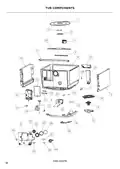
- Page 10: TUB COMPONENTS
- Page 11: Tub components reference part numbers and descriptions include various parts such as filters, screws, and kits. Key components listed are: - FP SS roll unload DD6010 - Filter plate O-ring DD6010 - Filter plate locknut DD6010 - Filter DD6010 - Kit rotor assembly DD6010 SP - Kit user interface DD6010 - Dispenser DD6010 - Kit stator assembly DD6010 SP - Flap valve drain 605 - Element 6010 Kawai 230V
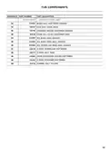
- Page 12: TUB COMPONENTS
- Page 13: Tub components reference part numbers and descriptions are listed. Includes various parts such as spray arm assembly, clamp hose, and fan housing. The document details specific components like the fan kit assembly and motor wire cover. It mentions several O-rings related to the water softener. Includes screws and washers for assembly. Various harnesses for different functionalities are included. The document references specific models like DD6010 and PH10. It lists components necessary for the operation of the water softener. The page continues with additional parts and descriptions. Overall, it serves as a reference for identifying and sourcing tub components.
- Page 14: Page 14
- Page 15: Tub components reference part numbers include various descriptions such as PCB, bung, harness, and hose. Key components listed are the water softener, overflow ring seals, and O rings. The document details specific part numbers associated with each component. It includes both assembly and sealing parts for the water softener system. The list provides a comprehensive overview of the necessary components for assembly and maintenance.
- Page 16: Page 16
- Page 17: Basket and rack components reference part numbers and descriptions are provided. Baserack assembly details include various components such as combs and clips. Main comb right and left assemblies are specified for the DD6010 model. Clip fold down parts are included in multiple assemblies. Crock ins PA 60 assembly is part of the components listed. Trapdoor assembly kit details are provided, including clips and wire loops. Rack cup assemblies for left and right sides are mentioned. Various clip kits and components are included for flexibility and functionality. The document continues with additional details on components.
- Page 18: Page 18
- Page 19: Basket and rack components reference part number. Part description includes basket cutlery 60 assembly mid-grey. Insert ST C basket 60 mid-grey. Insert tablet 60 mid-grey. Support glass clip-on.
- Page 20: Page 20
- Page 21: Installation components include various parts necessary for setup. Key components listed are clamp hose, support drain hose, and drain spigot connectors. The document details specific part numbers and descriptions for each component. Included items range from screws and clips to installation tabs. The installation kits cover both single and double configurations. Additional tools and materials are specified for proper installation. The document also references service and warranty information. Each part is identified with a unique reference number for easy tracking. The list emphasizes the importance of having all components for successful installation. Overall, the document serves as a guide for assembling necessary parts for the installation process.

BOSCH SMI6TCS00E Dishwasher

FRIGIDAIRE FFBD2406NB Full Console Dishwasher

BOSCH SMI6ECS10E Dishwasher

BOSCH SMS4EMI01E Dishwasher

IKEA SBE8596Z0E DISKAD PROFFSIG Dishwasher

FISHER AND PAYKEL DD24DCTW9 Dishwasher

BOSCH 300 Series 24 Front Dishwasher

BOSCH SPV6HMX5MR Dishwasher

Fisher and Paykel DW60FC6X1 Dishwasher

bellini BDW96W, BDW96X Series 45cm Dishwasher