
CAFE CDD220P2WS1 Energy Star Smart Drawer Dishwasher



TM
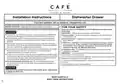
Installation Instructions
Dishwasher Drawer
If you have questions, visit our website at: cafeappliances.com
BEFORE YOU BEGIN - Read these instructions completely and carefully.
FOR YOUR SAFETY
Read and observe all WARNINGS and CAUTIONS shown throughout these
instructions.
WARNING
IMPORTANT – Observe all governing codes and ordinances.
Ŷ
Ŷ
To reduce the risk of electric shock, fire, or injury to persons, the installer must
ensure that the dishwasher is completely enclosed at the time of installation.
ŶꢀNꢀ ote to Installer – Be sure to leave these instructions for the consumer’s and
local inspector’s use.
FOR PERSONAL SAFETY: Remove house fuse or open circuit breaker before
beginning installation. Do not use an extension cord or adapter plug with this
appliance.
ŶꢀNꢀ ote to Consumer – Keep these instructions with your Owner’s Manual for
future reference.
ŶꢀSꢀ kill Level – Installation of this dishwasher requires basic mechanical, electrical
and plumbing skills. Proper installation is the responsibility of the installer.
Product failure due to improper installation is not covered under the GE
Appliances Warranty. See Warranty information.
Ŷ
Ŷ
Ŷ
The improper connection of the equipment grounding conductor can result in a
risk of electric shock. Check with a qualified electrician or service representative
if you are in doubt that the appliance is properly grounded.
If house wiring is not 2-wire with ground, a ground must be provided by the installer.
When house wiring is aluminum, be sure to use UL-Listed anti-oxidant
compound and aluminum-to-copper connectors.
ŶꢀCꢀ ompletion Time – 1 to 3 Hours. New installations require more time than
replacement installations.
IMPORTANT – The dishwasher MUST be installed to allow for future removal from
the enclosure if service is required.
To reduce the risk of electric shock, fire, or injury to persons, the installer should
check to ensure that wires are not pinched or damaged, the house wiring is attached
to the dishwasher through a strain relief, and all electrical connections made at
the time of install are contained inside of the terminal block cover.
For models equipped with power cord: Do not modify the plug provided
with the appliance; if it will not fit the outlet, have a proper outlet installed by a
qualified technician.
Care should be exercised when the appliance is installed or removed, to reduce the
likelihood of damage to the power supply cord.
If you received a damaged dishwasher, you should immediately contact your dealer
or builder.
Your dishwasher is a water heating appliance.
Ŷ
CAUTION
While performing installations described in this booklet, gloves, safety glasses
or goggles should be worn.
READ CAREFULLY
KEEP THESE INSTRUCTIONS


| General | Details |
|---|---|
| Name | CAFE CDD220P2WS1 Energy Star Smart Drawer Dishwasher |
| Make | Cafe |
| Language | English |
| Filetype | PDF (Download) |
| File size | 3.61 MB |
 (1 votes, average: 5.00 out of 5)
 Loading...

CAFE CDD220P2WS1 Smart Drawer Dishwasher

CAFE CDD220P4WW2 Smart Drawer Dishwasher

CAFE CDD220P2WS1 Energy Star Smart Drawer Dishwasher Overview
Summary of Contents
- Page 1: Installation instructions for the dishwasher drawer are provided. Before beginning, read the instructions completely and carefully. Observe all warnings and cautions throughout the instructions for safety. The installer must ensure the dishwasher is completely enclosed at the time of installation to reduce the risk of electric shock, fire, or injury. Remove house fuse or open circuit breaker before beginning installation. Installation requires basic mechanical, electrical, and plumbing skills. Improper installation may not be covered under warranty. Ensure proper grounding of the appliance to avoid electric shock. The dishwasher must be installed to allow for future removal if service is required. Safety precautions, such as wearing gloves and safety glasses, should be taken during installation.
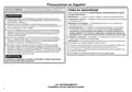
- Page 2: Precauciones en español Antes de comenzar, lea estas instrucciones en su totalidad y atentamente. Para su seguridad, lea y cumpla con todas las advertencias y precauciones que figuran en estas instrucciones. Cumpla con todos los códigos y ordenanzas gubernamentales. Para reducir el riesgo de descarga eléctrica, incendio o lesiones a personas, el instalador debe asegurarse de que el lavaplatos esté completamente cerrado en el momento de la instalación. Nota para el instalador: Asegúrese de entregar estas instrucciones al consumidor y al inspector local. Para seguridad personal, quite el fusible o abra el interruptor de circuitos antes de comenzar la instalación. La instalación de este lavavajillas requiere un nivel básico de habilidades mecánicas, eléctricas y de plomería. El lavavajillas debe ser instalado para permitir el retiro futuro de su ubicación, si se requiere realizar el servicio técnico. Se deberá tener cuidado cuando el electrodoméstico sea instalado o retirado, a fin de reducir la posibilidad de daños sobre el cable de suministro eléctrico. Al realizar las instalaciones descritas en este folleto, se deben usar guantes, gafas de seguridad o gafas protectoras.
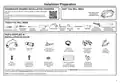
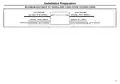
- Page 3: Installation preparation Dishwasher drawer installation overview This video provides an overview of what is needed to install a dishwasher drawer. It is intended as an overview only of the installation process and is not intended to be used as a guide on how to install the dishwasher drawer yourself. Tools you will need include a hammer, flush edge wire cutters, Phillips-head screwdriver, flat head screwdriver, pliers, carpenter’s square, drill and bits, measuring tape, flashlight, level, safety glasses, and gloves. Parts supplied in installation package include a drain hose support, drain hose joiner, wire clips, clamp, side mounting bracket kit, optional top mounting brackets, Phillips screws, bottom fixing screws and metal washers, rubber washer for inlet hose, moisture protection tape, and hexagonal socket for feet adjustment. If the drain hoses supplied are not long enough to reach your services, you must use a drain hose extension kit. Consider recycling options for your appliance packaging material.
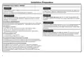
- Page 4: Installation preparation includes essential electrical wiring guidelines. Improper connection of the equipment grounding conductor can result in a risk of electric shock. Remove house fuse or open circuit breaker before beginning installation for personal safety. Do not use an extension cord or adapter plug with this appliance. Ensure that the electrical connection and wire size conform to the National Electric Code and local codes. This appliance must have a 120V, 60Hz, AC-only, 15-ampere or 20-ampere, fused electrical supply. Wiring must be 2 wire with ground and rated for 75°C (167°F). If the electrical supply does not meet the requirements, call a licensed electrician before proceeding. The appliance must be connected to a grounded metal, permanent wiring system or an equipment-grounding conductor. Grounding will reduce the risk of electric shock by providing a path of least resistance for electric current.
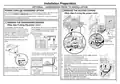
- Page 5: Installation preparation Power cord or hardwired option We recommend the use of the power cord. If using the power cord option, skip steps 1-5. If you elect to hardwire the dishwasher drawer, follow steps 1-5. In preparation for removing the dishwasher drawer, place a sturdy box nearby. Remove the drawer and place it on the covered sturdy box. Do not move or rest the drawer too far to prevent strain on its rear connectors. Carefully pull out the electronics module and rest it on the chassis base. Only unscrew the white and black terminals two turns; the green wire requires the screw to be removed.
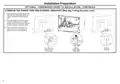
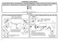
- Page 6: Installation preparation Optional - hardwiring prior to installation Remove the power cord and external knockout Skip step if using the power cord. From the outside, cut the power cord collar off flush at its base using wire cutters. Discard the exterior power cord. From the inside, remove the power cord/strain relief from its U-shaped retainer slot in the base pan. Discard the interior power cord/strain relief. From the outside, knock out the external knockout in the base pan using a hammer and screwdriver.
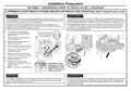
- Page 7: Installation preparation Terminate house wiring as shown and replace module and covers. Skip step if using the power cord. The improper connection of the equipment grounding conductor can result in a risk of electric shock. If house wiring is not 2-wire with ground, a ground must be provided by the installer. When house wiring is aluminum, be sure to use UL-Listed anti-oxidant compound and aluminum-to-copper connectors. Ensure wiring is routed through or under housing ribs. Screw down the black, white and green wires correctly. Replace the screw securing the electronics module. Ensure house wires are routed underneath all other harness wiring from the electronics module. Both ring terminals must be replaced and the Ground (green or bare) wire clamped under the Green Ground Screw.
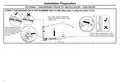
- Page 8: Installation preparation involves optional hardwiring prior to installation. Refit the drawer onto the runners and close. Skip the step if using the power cord. Lift or rotate counter-clockwise the drawer back onto the drawer runners on either side. Before refitting the drawer, ensure the hoses are not twisted and the latches at the rear of each drawer runner are facing forward. Pull the release tabs forward on both sides. Ensure the tabs are fully pulled forward and click into place.
- Page 9: Page 9
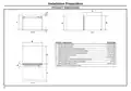
- Page 10: Installation preparation Product dimensions Overall height of product Overall width of product Overall depth of product (excluding handle) Depth of chassis (to back of front drawer panel) Depth of drawer front panel (including handle) Height of drawer front panel Height of chassis Ventilation gap between drawer front panels
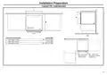
- Page 11: Installation preparation involves understanding cabinetry dimensions. Minimum clearances from adjacent cabinetry are essential for proper installation. The inside height of the cavity should be a minimum of 17-15/16” (456 mm). The inside width of the cavity should be 23-5/8” (600 mm). The inside depth of the cavity should be a minimum of 22-13/16” (580 mm). A minimum clearance of 1/2” (13 mm) from a corner cabinet is required. A minimum clearance of 1/16” (2 mm) to adjacent cabinet doors is necessary. Bracket slots are indicated for installation purposes. Cabinetry dimensions are provided in both inches and millimeters. Clearances are crucial for ensuring functionality and accessibility.
- Page 12: Installation preparation includes cavity preparation and countertop considerations. Moisture protection tape must be applied. The recommended hot water temperature is a maximum of 140°F (60°C). A supplied hose connects to a compression fitting. Marks indicate formed bracket screw locations for securing by drawer removal. If there is no side partition, timber bracing can be constructed for securing. Water pressure should be a maximum of 1 MPa (145 psi) and a minimum of 0.03 MPa (4.3 psi). Incorrect placement of the hole can damage hoses. The power outlet must be located in a cabinet adjacent to the dishwasher cavity. If the hole is through wood, ensure its edges are smooth and rounded.
- Page 13: Installation preparation involves understanding the maximum distance of hoses and cords from the chassis edge. The left-hand side has a drain hose measuring 70-1/2” (1800mm) and an inlet hose of 49” (1250mm). The right-hand side features a drain hose of 78-1/2” (2000mm) and an inlet hose of 64-3/4” (1650mm). Power cord specifications are also provided, although specific measurements are not listed.
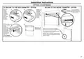
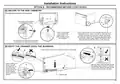
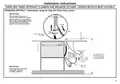
- Page 14: Installation instructions provide guidance on securing the unit without dishwasher drawer removal for frameless cabinetry. Choose the most suitable installation method, A or B. For method A, attach side mounting brackets and pull hoses through before pushing the unit into the cavity. Ensure all four side mounting brackets are securely clipped into their slots. Optional: Attach two top mounting brackets before sliding the product into the cavity. When fitting brackets, ensure the ends are not pushed down into the chassis. The mounting slots are in pairs, with brackets needing to match their corresponding slots. Level the floor of the cavity before installation. If the product cannot be pushed in far enough, rearrange hoses and cord instead of using excessive force. Ensure hoses and cord do not get kinked or twisted during installation.
- Page 15: Installation instructions provide guidance for securing cabinetry. Option A details the process for installation. The drawer should be opened halfway during installation. Replace the grey rubber plug into the trim moulding with the trim seal facing correctly. Top mounting brackets can bend upwards a maximum of 3/8” (10 mm). Use a flat bladed screwdriver to pry the grey rubber plug out of the trim moulding. Drill pilot holes and use a Phillips screwdriver to secure the side mounting bracket to the cabinetry. Repeat the securing process for all four brackets. After securing to the cabinetry, ensure the insulation is repositioned correctly. Avoid damaging the rubber trim seal during installation.
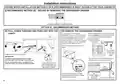
- Page 16: Installation instructions provide guidance on securing the dishwasher drawer. Choose the recommended installation method B for your cabinetry. Remove the dishwasher drawer by lifting it off its runners. Place the drawer upright on a covered sturdy box nearby. Ensure the box is covered with a towel for protection. Pull the dishwasher drawer out until it stops before pushing the runners back in. Level the floor of the cavity before installation. Avoid straining the rear connectors of the drawer during removal. Rearrange hoses and cords if the product cannot be pushed in far enough. Ensure hoses and cords do not get kinked or twisted during installation.
- Page 17: Installation instructions for securing the product to the side cabinetry are provided. The product has three pairs of fixing points. Ensure the sound insulation is repositioned correctly. Use 1-1/2” (38mm) fixing screws and washers for the bottom fixing holes. If applicable, use a screw in the slot on each side first for better alignment. Loosely screw the unit into place, check alignment, and then tighten screws. Refit the drawer onto the runners after ensuring hoses are not twisted. Ensure the latches at the rear of each drawer runner are facing forward before refitting. Pull the release tabs forward on both sides to secure the drawer. Make sure the tabs are fully pulled forward and click into place.
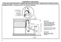
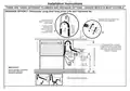
- Page 18: Installation instructions outline three different plumbing and drainage options. Drainage option 1 involves using a dishwasher and a 1-1/2” (38 mm) standpipe. The drain hose should be secured to the back wall at the correct height. If space is limited, the hose can be pushed through the drain hose support to the required height. It is important to install the drain hose as close to the underside of the countertop as possible to prevent waste from re-entering the drain hose. The drain hose must not extend into water retained in the trap; an air gap is necessary to prevent wastewater from siphoning back into the tub. Ensure that the drain connection complies with local plumbing regulations.
- Page 19: Installation instructions provide essential guidance for plumbing and drainage options. There are three different plumbing and drainage options to choose from. Drainage option 2 involves using an air gap with a drain hose joiner. It is recommended to use a commercially available air gap kit. Installing two single drawers allows for totally separate draining and eliminates possible cross draining problems. The drain hose should be secured to the air gap. The maximum height to the top of the air gap is 37-3/8” (950 mm). Ensure that the drain connection complies with local plumbing regulations.
- Page 20: Installation instructions provide essential guidance for plumbing and drainage options. There are three different plumbing and drainage options to choose from. Drainage option 3 involves using a drain hose joiner onto the sink trap or waste tee. A supplied drain hose joiner is included for this purpose. The drain hose should be screwed into a 3/4” (19 mm) waste tee. Ensure the drain hose is routed straight to the joiner to prevent waste water accumulation. It is important to comply with local plumbing regulations for the drain connection. Do not shorten the inlet hose.
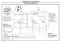
- Page 21: Installation instructions for under sink installation require specific dimensions and utility connections. Under sink installation needs a base for the dishwasher drawer and side walls for mounting. The top filler face board must be a minimum of 10-1/4 inches. Utility lines must run above and adjacent to the dishwasher, not behind it. The rough cabinet opening should be at least 24 inches deep, 24 inches wide, and approximately 34-1/4 inches in height. The dishwasher must be fully enclosed on the top, sides, and back. Electrical connection strain relief is located on the rear left side of the dishwasher. For power cord connections, a 3-prong grounding type receptacle should be installed near the dishwasher. Water lines to the sink faucet and drain can be routed through designated areas. Refer to the installation instructions for fill, drain, and electrical connections.
- Page 22: Installation instructions include connecting water and switching the dishwasher on. Ensure the supplied rubber washer is fitted inside the coupling when connecting the inlet hose to hot water. Check for excessive water remaining above the filter plate after the rinse cycle, indicated as an A3 fault. Verify that the drain hose is not kinked and that the waste connection is not blocked. If there is no water supply, indicated as an A1 fault, check that water is connected and turned on. Continuous beeping indicates a fault; refer to the Owner’s Manual for further information. If no program indicator lights up when the drawer is opened, ensure power is connected and switched on. Check for leaks around water supply and drainage connections, ensuring hoses and clamps are properly fitted. If the product is tipping, ensure it is secured to the cabinetry. For misaligned front panels, check and re-level the product and cabinetry.
- Page 23: Installation instructions outline the final checklist to be completed by the installer. Check all parts are installed and ensure the power and water supplies are turned on. You should hear a beep and see a program indicator light up on the internal control panel. Ensure all panels and parts are secure and that final electrical tests have been conducted according to local regulations. Check that the spray arms are in place, mounted correctly, and free to rotate. Ensure the product is level, securely fastened to the cabinetry, and opens and closes freely. The inlet hose to the water supply must have a rubber washer fitted and tightened properly. Ensure any knockouts or plugs in the drain connection have been removed and the connection is made. Add three cups of water into the drawer and press the program to start the rinse program. After the rinse program has finished, ensure the dishwasher has run and drained correctly.

BOSCH SMU6ZDW76S Dishwasher

Midea MDC17P2BWW Dishwasher
BOSCH SMS8ZDI86M Dishwasher

Whirlpool RUDXYL Dishwasher

Hisense HSCE14FS Dishwasher

MAYTAG PDBTT49AWW Dishwasher

Midea MDF18A1AWW Dishwasher

Electrolux 520518 Veetsan Hood Type Dishwasher

FRIGIDAIRE A23587501 24-Inch Dishwasher

FISHER PAYKEL DD24SCTW9 N Single DishDrawer Dishwasher