Home > Fisher & Paykel > FISHER & PAYKEL DW60UNT4X2 Built-Under Dishwasher
FISHER & PAYKEL DW60UNT4X2 Built-Under Dishwasher


BUILT-UNDER DISHWASHER
CONTEMPORARY
DW60UNT4X2, DW60UNT4B2, DW60UZT4B2 models
INSTALLATION GUIDE
NZ AU

| General | Details |
|---|---|
| Name | FISHER & PAYKEL DW60UNT4X2 Built-Under Dishwasher |
| Make | Fisher & Paykel |
| Language | English |
| Filetype | PDF (Download) |
| File size | 0.8 MB |


FISHER PAYKEL DD24DCHTX9 N Dishwasher

FISHER PAYKEL DD24DCTW9N Dishwasher

FISHER PAYKEL DD24SCTX9 N Dishwasher

FISHER PAYKEL DD60SCHX9 Dishwasher

FISHER PAYKEL DD24DI9N Sanitize Dishwasher

FISHER PAYKEL DD24SV2T9N Sanitize Tall Dishwasher

FISHER PAYKEL DD60DAX9 Dishwasher

FISHER PAYKEL DD60SDFHTX9 Dishwasher

FISHER PAYKEL DW24UT4I2 Dishwasher

FISHER PAYKEL DD24SVT9 Dishwasher

FISHER & PAYKEL DW60UNT4X2 Built-Under Dishwasher Overview
Summary of Contents
- Page 1: Built-under dishwasher Contemporary DW60UNT4X2, DW60UNT4B2, DW60UZT4B2 models Installation guide
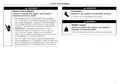
- Page 2: Safety and warnings Electric shock hazard Cut hazard Failure to follow this advice may result in electrical shock or death. Failure to use caution could result in injury. Take care – panel edges are sharp. This appliance must be earthed. Improper connection of the equipment-earthing conductor can result in a risk of electric shock. Do not attempt to lift this product unassisted. Do not modify the power supply plug provided with the appliance.
- Page 3: Safety and warnings Failure to install the custom panels correctly could invalidate any warranty or liability claims. To reduce the risk of fire, injury to persons or damage when using the appliance, follow the important safety instructions listed below. Installation of this dishwasher requires basic mechanical and electrical skills. Installation must comply with your local building and electricity regulations. At the completion of the dishwasher installation, the Installer must perform the Final Checklist. Do not repair or replace any part of the appliance unless specifically recommended in this guide. Ensure all water connections are turned off. The dishwasher must be installed to allow for future removal from the enclosure if service is required. This dishwasher is manufactured for indoor use only. Do not operate this appliance if it is damaged, malfunctioning, partially disassembled or has missing or broken parts.
- Page 4: Components required include various parts and tools necessary for assembly. Keep all packing materials until the unit has been inspected. Inspect the product to ensure there is no shipping damage. Contact the dealer or retailer if any damage is detected. Fisher & Paykel is not responsible for shipping damage. Tools supplied include powered driver, cross-head screwdriver, flat-head screwdriver, and box cutter. Additional supplied items include spacers, moisture protection tape, screws, sound seal, toe kick brackets, pre-finished toe kick assembly, drain hose support, and washers.
- Page 5: Product dimensions include overall height, width, and depth measurements. Overall height ranges from 857 to 917 mm. Overall width is 597 mm. Overall depth is 574 mm. Height of chassis is specified. Depth of chassis is provided. Height of feet varies from 0 to 60 mm. Height of toe kick panel is 857 mm. Custom and pre-finished panel dimensions are listed. Actual product dimensions may vary by 2 mm.
- Page 6: Cabinetry dimensions and clearances are essential for installation. Connections can be located in an adjacent cabinet on either side of the dishwasher. Minimum inside height is 857 mm. Minimum inside width is 600 mm. Minimum overall depth is 580 mm. Minimum clearance to adjacent cupboard door is 2 mm. Minimum clearance to corner cupboard is 13 mm. Recommended height of adjacent cabinetry is between 713 mm and 794 mm. Height of toe kick area ranges from 65 mm to 200 mm. Refer to 'Plumbing & electrical considerations' and 'Cabinetry preparation' for service requirements.
- Page 7: Plumbing and electrical considerations Your services can be installed to either the left-hand or right-hand side of the product in an adjacent cabinet. The drain hose should not extend more than 4m. A longer drain hose will cause reduced performance. The dishwasher should not be connected to a water system where there is no temperature control, unless the system is fitted with a suitable tempering valve. The dishwasher must not be connected to an undersink high-pressure push-through hot water system, as damage to the system will result. Maximum water temperature: 60°C. Ensure water connection complies with local plumbing regulations. This dishwasher has anti-flood protection, which will stop the water flowing in the event of a leak within the machine.
- Page 8: Service access is important for the dishwasher installation. Locate the service holes on either side of the dishwasher as shown. Ensure edges are smooth and rounded if holes are created through wood. Fit an edge protector if holes are created through metal. Maximum distance between the rear of the cavity and service hole is specified. Maximum distance between the floor and service hole depends on the adjustment of leveling feet. Minimum diameter of the service hole is provided. Dimensions for service holes are given in millimeters. Cabinetry depth of 580mm is referenced for service hole placement. Proper installation ensures accessibility for service and maintenance.
- Page 9: Unpack product Ensure all minimum cabinetry and service specifications have been met and that all services will be accessible after installation. Dispose of packaging responsibly. Ensure cabinetry floor is free from bumps and obstructions that could prevent the dishwasher from sliding into the cavity. Remove the install kit, any internal packaging, all rubber bands and all tape. Align the supplied moisture protection tape to the cabinetry as shown. Ensure this area is free of debris before carefully applying the tape to the surface.
- Page 10: Push into cavity. Secure to cavity. Using a flat bladed screwdriver, turn to raise the leveling feet. Level the rear, outside legs first followed by the front legs. Loosely fit side fixing screws. Remove both screw covers before partially pushing the product into the cavity. If needed, adjust the dishwasher within the cavity before tightly securing in place. Check the product sits level within the cavity. Secure to benchtop using screws if possible. Select desired spacer width and cut to size.
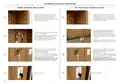
- Page 11: Install sound seal. Install toe kick. Align both sound seal sheets to the base of the dishwasher. Measure the distance between the floor and the base of the door. Score at the marked height, snap off excess material and smooth edges. Ensure door swing is unobstructed before securing the seals using the provided washers and screws. Ensure brackets are oriented correctly before fitting to the panel using screws. Measure the toe kick depth. Use Z to determine which tooth to bend back on each toe kick bracket. Align the brackets to the slots on the product and slide into place.
- Page 12: Install toe kick. Continuous toe kick panel. Custom toe kick panel. Mark the pilot hole locations for each bracket. Measure the centre of the panel and mark 237mm to each side. Align toe kick to product and ensure all door swing clearances have been met. Determine the height of the brackets by measuring the height of the lowest bracket hole against the toe kick panel. Ensure brackets are oriented correctly before fitting to the panel using 2 screws per bracket. Fit panel to surrounding cabinetry. Use the measurements to determine which tooth to bend back on each toe kick bracket.
- Page 13: Plumbing & electrical connection Sink trap/waste tee installation Install the drain hose support to the back wall, as close to the underside of the countertop as possible. Refer to 'Plumbing & electrical considerations' for minimum install heights. Ensure hose is routed straight to the trap. Ensure the drain hose does not extend into water retained in the trap; an air gap is required to prevent waste water from siphoning back into the tub. Unplug or drill out the waste tee before securing joiner to sink trap or waste tee. Ensure the rubber washer is fitted when connecting the inlet hose to the tap. Hand-tighten into place. Using a spanner or pliers, turn a further 180° to secure, avoiding over-tightening. Do not turn water supply on. The dishwasher must be powered on for the flood protection feature to be enabled.
- Page 14: Installer checklist Check all parts are installed correctly and are secure. Turn power and water supply on and open the dishwasher. Ensure all packaging, tape and rubber bands have been removed. Ensure all clearance gaps have been maintained. Ensure dishwasher is securely fastened to the cabinetry and door opens and closes freely with no resistance. Check the spray arm is in place, mounted correctly and rotates freely. Ensure any knock-outs or plugs in drain connection have been drilled out and drain connection has been made. The drain hose joiner must not support the weight of excess hose material. Ensure inlet hose has supplied rubber washer fitted, and that it is tightened. Ensure water supply is turned off until power is connected and turned on.

FISHER and PAYKEL DD60D2HNB9 Contemporary Dishwasher

BOSCH SHP87P Dishwasher

BOSCH SMS4HMC65M Dishwasher

FISHER PAYKEL DD60D2NX9 Dishwasher

Midea MDT24X2APR Dishwasher
lord D3 Dishwasher

Whirlpool WDT740SAL Dishwasher
FISHER PAYKEL DD24DI9N Sanitize Dishwasher

BOSCH SMH8ZB802E Dishwasher

FISHER AND PAYKEL DD24STX6HI1 Tall Dishwasher