Miele PFD 101 i Dishwasher User Manual

Installation plan
PFD 101 i
en - AU, NZ
M.-Nr. 11 882 830

| General | Details |
|---|---|
| Name | Miele PFD 101 i Dishwasher |
| Make | Miele |
| Language | English |
| Filetype | PDF (Download) |
| File size | 0.3 MB |


Miele PFD 103 SCi XXL XXL Dishwasher

Miele AK-CC 550A APFD 102 Dishwasher

Miele PFD 102 APFD 102 Dishwasher

Miele 11 836 740 Dishwasher

Miele PFD 401 U Commercial Dishwasher

Miele PLW 8683 Laboratory Dishwasher

Miele PFD 100 SmartBiz Free-Standing Dishwasher

Miele 12 668 930 Dishwasher

Miele PFD 102 i Dishwasher

Miele PFD 104 SCVi Dishwasher

Miele PFD 101 i Dishwasher Overview
Summary of Contents
- Page 1: Installation plan
- Page 2: Installation notes Installation requirements Environmental requirements Electrical connection Water connection Appliance dimensions and installation dimensions Connections Technical data Operating conditions Storage and transportation conditions
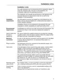
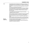
- Page 3: Installation notes provide essential information for safe installation and commissioning of the dishwasher. The installation plan includes dimensions, technical data, and site requirements for the dishwasher. Only Miele Customer Service, an authorized dealer, or a qualified specialist should install and commission the dishwasher. Installation must comply with valid regulations, relevant standards, and health and safety codes. Furniture and fittings in the room must be suitable for purpose due to potential condensate build-up. The supplied vapour barrier film protects the worktop from steam damage when the door is opened. All electrical connection work must be performed by qualified personnel. The dishwasher should be connected via a suitably rated plug and socket or hard-wired with a disconnecting power switch. The power switch must have a contact gap of at least 3 mm and be accessible after installation. It is recommended to use a residual current device (RCD) for increased safety.
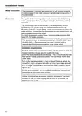
- Page 4: Installation notes The dishwasher must only be connected to fully vented pipework. A brief increase in the water pressure can damage components of the dishwasher. The quality of the incoming water must correspond to the drinking water specification of the country. The dishwasher must be connected to the water supply in strict accordance with current local and national requirements. It can be connected to cold or hot water supplies. Connecting the dishwasher to a hot water supply will reduce programme running times. Dynamic water pressure of at least 200 kPa is required for short programme running times. The dual check valve supplied separately must be installed between the tap and the water inlet hose. Turn on the tap gradually to test for leaks. The tap should remain accessible once the dishwasher has been installed.
- Page 5: Installation notes The dishwasher drain hose should be connected to a separate on-site drainage system for the dishwasher only. If a separate connection is not available, it is recommended to connect the hose to a dual-chamber siphon. If the hose is to be fitted directly to the drainage system on site, use the hose clip supplied with the dishwasher. The on-site connector for the drain hose can be adapted to different hose diameters. If the connector extends more than 30 mm into the drain hose, it must be shortened to prevent blockage. Lay the drain hose so that it does not kink and is not subjected to pressure or tension. If the on-site drain connection is situated lower than the guide path for the lower basket rollers, a siphoning effect can occur. In this case, lay the drain hose with a bend so that its highest point is at least level with the guide path for the lower basket rollers. An external dispensing module for liquid cleaning agents can be connected to the back of the dishwasher. The dispensing module is available as an optional accessory and is supplied with installation instructions.
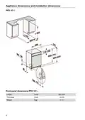
- Page 6: Appliance dimensions and installation dimensions Front panel dimensions PFD 101 i Length Thickness Weight
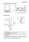
- Page 7: Connections on the back of the appliance include various on-site connections. Electrical connection is necessary for the appliance to function properly. External dispensing requires a power supply connection. Equipotential bonding is important for safety. Waste water management is a key consideration. Connections for cold or hot water must be established. There is a connection for dispensing hose sealed with a blind stopper. The dispenser connector is supplied with the dispensing module.
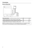
- Page 8: Connections External dispensing Max. delivery head Length of dispenser hose, DOS module to suction lance Length of dispenser hose, back of appliance to DOS module Length of power cable, back of appliance to DOS module Place the container on the floor next to the cleaning machine or in an adjacent cabinet. The container must not be placed on top of or above the cleaning machine.
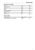
- Page 9: Technical data Dimensions and weights Height: 805 mm Width: 598 mm Depth: 570 mm Weight: 115 kg Max. floor load: 1000 N Sound power level: 46 dB(A) re 1 pW Sound pressure level in the workplace: 34.1 dB(A)
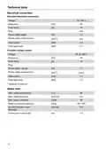
- Page 10: Technical data Electrical connection Standard electrical connection Voltage: AC 230 V Frequency: 50 Hz Fuse rating: 10 A Power cable length: 1.7 m Heat output: Total rated load 3 kW Possible voltage variant: 3N AC 400 V Max. water temperature: 60 °C Max. water hardness: 36 °dH
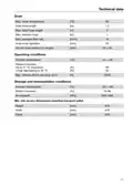
- Page 11: Technical data Max. water temperature: 82 °C Drain hose length: 1.5 m Max. drain hose length: 1 m Max. delivery head: 10 l/min Hose inner diameter: 22 mm Operating conditions: Ambient temperature +5 – +40 °C Relative humidity: Up to 31 °C, maximum 80% Max. altitude above sea level: 4000 m Storage and transportation conditions: Ambient temperature -20 – +60 °C Min. site access dimensions including transport pallet: Height 970 mm, Width 670 mm, Depth 670 mm
- Page 12: Page 12

BOSCH SMS8ZCI00X Dishwasher

BOSCH SMH4HVX00E Dishwasher

BOSCH SMS2HVW66G Dishwasher

BOSCH SMS6ZCW10E Dishwasher

FISHER AND PAYKEL DD24DCTW9 Dishwasher

FISHER PAYKEL DD24SAX9 N Single DishDrawer™ Dishwasher

BOSCH SMS26DW00T Dishwasher

ggmgastro GLOZ50 Undercounter Dishwasher

BOSCH SMS4IMI62T Dishwasher

CMA DISHMACHINES CMA H-1X Undercounter Dishwasher