CMA-66 EST-66 Conveyor Dishwasher


| General | Details |
|---|---|
| Name | CMA-66 EST-66 Conveyor Dishwasher |
| Make | CMA |
| Language | English |
| Filetype | PDF (Download) |
| File size | 0.59 MB |


CMA UC65e M3 Undercounter Dishwasher

CMA H-1X Undercounter Dishwasher

CMA EST-FL1 EST Front Loader Water Dishwasher

CMA-66 EST-66 Conveyor Dishwasher Overview
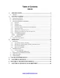
Summary of Contents
- Page 1: Page 1
- Page 2: Specifications Getting started Introduction to CMA-66 Receiving and installation Installation notes Pump impeller note Safety tips for the CMA-66 Initial setup Beginning operation Regular service and maintenance checklist
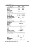
- Page 3: Specifications Water consumption per rack: .8 gal. (L.T.), .94 gal. (H.T.) Operating capacity: 192 gal. per hour Conveyor speed: feet per minute Operating temperature: 140° - 150° F (wash), 180° - 195° F (final rinse) Water requirements: Inlet temperature (min) 140° F, drain size 2” Pump capacity: 52 GPM (each) Dimensions: Depth 25-1/8”, width 66”, height 55 ½”-56 ½” Electrical rating: 208/240 volts, 1 phase Heater: 10 kW Shipping weight: 750#
- Page 4: Getting Started Introduction to CMA-66 The CMA-66 is designed to give maximum cleaning in 66 inches. Energy costs for running the CMA-66 have been greatly reduced by the introduction of stage washing. The supply water to the CMA-66L must be a minimum of 140°F, while the CMA-66H requires two supply lines. The CMA-66 features a scrap tray that may be emptied on a periodic basis without interruption of the flow of work. The CMA-66L is designed to deliver 0.8 gallons of fresh rinse water and the CMA-66H is designed to deliver 0.94 gallons of fresh rinse water for each rack. A single-phase CMA-66 is available for installations where the only power available is 208V-230V/1-PH. This manual is structured to provide a complete reference guide to the CMA-66. The first section explains how the machine is packaged and what to look for when receiving the machine. The Operation Section of the manual may be used for instruction and procedures when required.
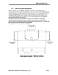
- Page 5: Getting started When you receive your new CMA-66, complete the assembly by installing the scrap tray assembly with its overflow chute, the two wrapper shields and the curtain rods. Remove the left and right stainless steel wrapper shields and bolt them in place with the nuts and bolts provided. The wrapper shield with the extra curtain clamps mounts onto the dirty end of the machine. Next, mount the scrap tray assembly and overflow chute into position. All of the spray arms should be inserted and in place over the wash tank compartments. There are a total of seven curtains used in the CMA-66; two are long-narrow, two are short-wide. The two long-narrow curtains have shorter rods than the other two curtains. The short rods hold the curtains at the entrance and exit of the machine.
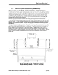
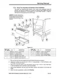
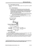
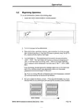
- Page 6: Getting started When you receive your new CMA-66, complete the assembly by installing the scrap tray assembly with its overflow chute, the two wrapper shields, and the curtain rods. Remove the left and right stainless steel wrapper shields and bolt them in place with the nuts and bolts provided. The wrapper shield with the extra curtain clamps mounts onto the dirty end of the machine. Next, mount the scrap tray assembly and overflow chute into position. All of the spray arms should be inserted and in place over the wash tank compartments. There are a total of seven curtains used in the CMA-66; two are long-narrow, four are long-wide, and one is short. The two long-narrow curtains and the one short curtain have shorter rods than the other four (long-wide) curtains. The sketch below lists curtain positions 1 through 6, representing a flow from left-to-right. If the dish flow is from left-to-right, the proper sequence for the placement of the curtains would be: long-narrow curtain in the first position; short curtain in the second position; two short-wide curtains in the third position; two short-wide curtains in the fourth position; and a long-narrow curtain in the sixth position.
- Page 7: Getting Started A 3-phase 208-240 volt AC, 60 Hz dedicated circuit should be used to supply electrical energy to the CMA-66 dishwasher. Connect the wire that has the highest voltage (stinger lead) to the main contactor’s power terminal L2. The water supply connection is made with a ½” hot water line to the water supply inlet on the top of the machine. The water supplied to the machine must be a minimum of 140° F for the CMA-66L and a minimum of 180° F for the CMA-66H. The High Temp machine (CMA-66H) comes with two water supply line connections. There are two 2” drain connections to be made. Tables must slant into the machine for proper drainage. The scrap tray assembly is placed inside the machine for shipping. Electrical and plumbing connections must be made by a qualified person who will comply with all available Federal, State, and Local Health, Electrical, Plumbing and Safety codes.
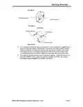
- Page 8: Getting started On a 3-phase machine, the water pump motors are also 3-phase and can rotate in either direction depending on the terminal connections. Check the direction of rotation by removing the dust cap on the back of the motor. The motors must turn clockwise when looking at the shaft from the back of each motor. To change the direction of rotation, switch any two power lead wires at the motor. The machine must be running to set the pressure regulator. While the machine is in the final rinse cycle, adjust the pressure regulator to 20 PSI. See section 3.1.3 Rinse Pressure Regulator for detailed instructions.
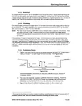
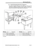
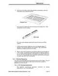
- Page 9: Getting started The scrap tray assembly and overflow chute can easily be installed by executing the following steps. Figure 2.3.4 illustrates the assembly as it would appear for a Left-to-Right machine. Caution: For proper spacing, the SS flat washer must not be located between the head of the trusshead bolt and the inside of the machine. Remove the items from their packing and verify that all the pieces are present. Attach the overflow chute with the five ¼-20 X ½” trusshead bolts, ¼” SS flat washers, and ¼-20 nylon lock nuts provided. Secure the scrap trap holder to the dishmachine using the four ¼-20 X ½” hex head bolts, ¼” SS flat washers, and ¼-20 nylon lock nuts provided. Set the scrap trap body—with the scrap trap drawer inserted—into position on the scrap trap holder. Attach the drain as specified in section 2.3.2 Plumbing.
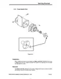
- Page 10: Getting started When installing the water pump impeller, the Nylon Lock Nut must be in place to prevent the impeller from spinning off of the shaft and damaging the motor. The Nylon Lock Nut must be removed before attempting to remove the water pump impeller.
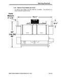
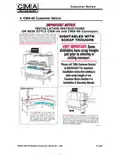
- Page 11: Getting started An optional hood adapter set (P/N 13901.82) is available. The dimensions for proper installation are given below. Measure 4” x 16” Leg adjustment 66”
- Page 12: Getting started The optional freestanding scrap trap and adaptor kit are available for installations where the space is insufficient to accommodate the standard side-mounted scrap trap or where drain access is easier by locating the scrap trap some distance away from the dishmachine.
- Page 13: Getting started Installation of the accessory chemical pumps must be performed by qualified personnel. Checkvalves should be installed directly at the mixing chamber coupling. There are two 1/8” FPT mounting holes provided, which will position the checkvalves parallel to the machine. Simply remove the plug from the mounting hole and install the checkvalve—be sure to use a proper sealing compound or Teflon tape on the threads. There are two mounting holes provided on the mixing chamber coupling, one for rinse chemical and one for sanitizer chemical. Connect only to the primary side of the Listed Class 2 Transformer, 208-230 VAC, 60 Hz, 100 VA maximum load. The 10kW heater located in the wash/final rinse tank has an independent power switch. As a safety precaution, if the wash tank is drained while the heater is left on, the thermostat receives a signal to turn off the heater. The heater switch should always be turned off when the machine is not in operation. Electrical and plumbing connections must be made by a qualified person who will comply with all available Federal, State, and Local Health, Electrical, Plumbing and Safety codes.
- Page 14: Getting Started Safety Always turn off the circuit breaker at the wall when working on this dishmachine. Do not get in the path of the conveyor rocker arm or the conveyor’s moving bar. Do not reach into the rocker arm area without first making sure the dishmachine is turned off at the circuit breaker. Do not open the front door when the machine is in operation. Avoid spraying water on or around the electrical control box on the top of the machine. When cleaning, do not spray water directly on the motors. When removing the final rinse arms for cleaning, exercise caution.
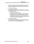
- Page 15: Operation Initial Setup Auto Fill Timer/ Auto Re-Fill Timer Both timers for the CMA-44 are set at the factory, but may need to be adjusted at the time of installation depending on supply water pressure. When the power switch is activated, the machine should fill until water begins to overflow into the scrap tray. Adjust the timer block marked “Auto Fill Timer” to shut off when water is observed flowing into the scrap tray. The auto re-fill system must be set to fill the wash tank if there is a loss in water. If the water level drops to the level of the float switch located in the wash tank, the float switch will trigger the Auto Re-Fill timer. Adjust the Auto Re-Fill Timer by draining the wash tank manually until the float activates the Auto Re-Fill timer. When the auto re-fill is activated, the machine should fill until water begins to overflow into the pre-wash tank. Auto Fill/Auto Re-Fill can be adjusted by turning the potentiometer with a small flat blade screwdriver. Every time power is interrupted and restored, the Auto Fill Timer will reset and add an additional full charge of water.
- Page 16: Operation If at any time less than a full Auto Fill cycle is desired, the Auto-Fill can be interrupted by turning off the power to the machine. The CMA-66 requires a supply water pressure of 24 PSI minimum. Use the following procedure to adjust the rinse pressure to 20 PSI. Close the door on the machine. Turn the Power switch to the ON position. Actuate the final rinse trip switch to activate the water solenoid. Adjust the pressure regulator until the gauge reads 20 PSI. Always adjust “down” when setting this pressure regulator. The wash tank temperature for the CMA-66 is set at the factory. Perform steps in section 3.2 Beginning Operation to adjust the wash tank temperature.
- Page 17: Operation To run the dishmachine, perform the following steps: Close both drains (valve handles in vertical position). Turn on the power to the dishmachine. Open the fill-valve and fill the machine until it overflows out of the pre-wash tank into the scrap tray or, if the Auto Fill option is present, press the AUTO FILL switch to fill the machine with water. Turn the heater on. The temperature of the water in the tank should be 140°F – 150°F. The tank heater will maintain a minimum temperature of 140°F if the final rinse is providing 140°F – 150°F at all times. 150°F minimum will be maintained if the final rinse is 180°F – 195°F. If the thermostat needs adjustment, there is a thermostat adjustment access hole located on the cover. If you are having difficulty maintaining wash tank temperature, minimize the vent hood openings by closing off the dampers. Be sure to place the dishes correctly. If they become dislodged, they could interfere with the trip switch lever and interrupt the operation of the machine.
- Page 18: Operation At the end of the shift and after heavy periods of accumulation, clean the three strainer trays inside the machine. Also, at the end of each shift, remove and clean the six spray arms. When water becomes heavily soiled, drain the tanks and refill the machine. Check chemical buckets to ensure an adequate supply of detergent, rinse aid, and sanitizer. Verify that the pickup line is inserted into the correct bucket. Slide in a dish rack to activate the cycle start trip switch on the pre-wash end of the machine. The 60-second time-delay-off relay will hold the machine in run mode for 60 seconds after a rack releases the cycle start switch. The rinse and sanitizing agents are injected into the final rinse make-up water when the final rinse trip switch is activated. See dispenser manufacturing operational instructions for sanitizer adjustments for low temperature applications.
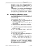
- Page 19: Operation The sanitizing pump operates when the fresh water enters the machine during final rinse. The water is treated at 50 PPM (parts per million). The pressure regulator is adjusted to 20-PSI. It is recommended that the 5-1/2% chemical solution be standardized for uniform dispensing of the sanitizing solution. Inside the control box is a labeled power block for the sanitizer and rinse aid. Regular service and maintenance checklist includes checking flatware and glasses. Check the interior condition of the machine with the circuit breaker turned off. The stainless steel inside the machine should be clean and shiny. Check the condition of the strainer trays for excessive garbage. Verify that the heater is working and check the thermostat setting.
- Page 20: Operation Replace all the strainer trays into their proper position and fill the machine. Place a rack into the machine and observe the spray pattern of the pre-wash, the wash, and the final rinse. Check the titration of the wash tank at this point. While the rack is in the final rinse, check for 50 PPM residual chlorine in the final rinse. Observe the final rinse vacuum breaker for leaks. Run a stemware or glass rack through the machine and check the results on the glassware. Check the condition of the chemical tubing from the peri-pump to the check valves. Observe the final rinse pressure at 20 PSI. Adjust if necessary. Check the condition of the chemical tubing coming from the detergent rinse and sani buckets. With the machine stopped, check the roller cam bearing on the conveyor.
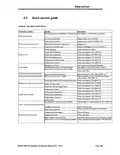
- Page 21: Operation Quick service guide Models: CMA 44/66 conveyor(s) Continuously cycles Manual/auto switch in manual mode or faulty Turn switch to auto position or replace Conveyor timer faulty Final rinse does not come on Machine only runs in manual mode Heater does not work Low or no pressure at final rinse arm
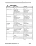
- Page 22: Operation Troubleshooting Bad motor or capacitor Replace defective motor Fuse is burned out Replace fuse Machine inoperative Replace reed switch Defective door reed switch Defective start reed switch Defective heater Low rinse water pressure or no rinse Check dispenser troubleshooting guide
- Page 23: Customer notice Model CMA-66 installation & operation manual rev. 1.09B
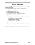
- Page 24: Customer notice Tips to save a service charge If the lessee of this equipment initiates a service call and it is subsequently determined that the problem does not relate to part failure or out of chemicals, there will be a minimum service charge for a service person to respond. It is recommended that you check the following items before initiating a service call: Circuit breaker position should be “ON”. Clogged drains (at any point in drain line). Lack of soft water (check salt level in brine tank). Lack of hot water due to valves shut off or incorrect thermostat settings. Failure of equipment unrelated to the machine. Abuse to equipment or failure to perform minimum cleaning requirements as outlined at time of installation.
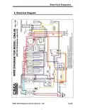
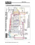
- Page 25: Electrical diagrams provide essential information for installation and operation. The document is focused on the model CMA-66. This is the installation and operation manual. The revision of the manual is 1.09B. The page number is 24.
- Page 26: Operation Electrical diagram (old models) Model CMA-66 installation & operation manual Rev. 1.09 B
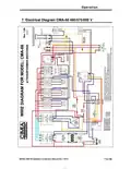
- Page 27: Operation Electrical diagram CMA-66 480/575/600 V MODEL CMA-66 installation & operation manual Rev. 1.09 B

BOSCH SMI2ITB33E Dishwasher

FISHER AND PAYKEL DD60DTX6I1 Dishwasher

HJC V31 Carbon Dishwasher

FISHER PAYKEL DD60D4HNX9 Dishwasher

GE APPLIANCES PDP715SYNFS Dishwasher

SILVERCREST SGW 860 A1 Table Top Dishwasher

Whirlpool 2B19 Dishwasher

IKEA RENGÖRA 204.756.05 Dishwasher

BOSCH SMS46NI10M Dishwasher

FISHER AND PAYKEL DD24STX6PX1 Dish Drawer Dishwasher