Home > CMA Dishmachines > CMA DISHMACHINES CMA-180 Rack Straight Dishwasher
CMA DISHMACHINES CMA-180 Rack Straight Dishwasher


MODELS CMA-180/180TALL
Including 480V MACHINES
PARTS MANUAL
Rev 2.09 03-22-22
C M A D I S H M A C H I N E S
1 2 7 0 0 K N O T T A V E N U E
GARDEN GROVE, CALIFORNIA 92841
8 0 0 - 8 5 4 - 6 4 1 7
FAX 714-895-2141
Buy Parts

| General | Details |
|---|---|
| Name | CMA DISHMACHINES CMA-180 Rack Straight Dishwasher |
| Make | CMA Dishmachines |
| Language | English |
| Filetype | PDF (Download) |
| File size | 0.87 MB |


CMA DISHMACHINES EST-44 Conveyor Dishwasher

CMA DISHMACHINES CMA-180UC Under Counter Dishwasher

CMA DISHMACHINES EST-AH Door Type Rack Low Dishwasher

CMA DISHMACHINES UC65e M3 Dishwasher

CMA DISHMACHINES CMA-180VL Dishwasher

CMA DISHMACHINES UC50e Dishwasher

CMA DISHMACHINES CMA-180 Dishwasher

CMA DISHMACHINES CMA-180UC Dishwasher

CMA DISHMACHINES H-1X Undercounter Dishwasher

CMA DISHMACHINES 180UC-3 Under Counter Dishwasher

CMA DISHMACHINES CMA-180 Rack Straight Dishwasher Overview
Summary of Contents
- Page 1: Models CMA-180/180TALL Including 480V machines Parts manual Rev 2.09 03-22-22 CMA dish machines
- Page 2: Model CMA-180 Parts manual Initial parts kit #1100.17 Exploded view drawings Straight frame system assembly Corner frame assembly Drain system assembly Plumbing system assembly Wash spray system Final rinse system Power switch bulb replacement instructions
- Page 3: Parts Manual Parts Kit CMA-180 Drain Stopper O-ring Pump Assy. 115/220V 60Hz (Open) Pump Seal Kit Rinse Arm w/ Bearings Spray Arm Assy CMA180 w/ bearings & end plugs Contactor 208/240V 20 Amp DP Micro Switch Illuminated Plug CMA-180/44 P Model CMA-180 Parts Manual Rev. 2.09
- Page 4: Exploded view drawings provide a detailed breakdown of the straight frame system assembly. The document includes item numbers, required quantities, part numbers, and descriptions for various components. Key components listed include the stand, door handles, door panels, and safety brackets. Additional parts include nylon lock nuts, hex bolts, and splash guards. The manual specifies the model CMA-180 and is identified as parts manual revision 2.09. The document also includes references to specific parts like the strainer basket and scrap trap drawer. It outlines the assembly requirements for the frame system. The information is structured to facilitate easy identification and ordering of parts. The page is part of a larger user manual focused on parts and assembly. There is a section indicating a link to buy parts.
- Page 5: Corner frame assembly includes various items and their descriptions. Key components include the stand, overflow, door panel corner, and door. Additional parts consist of gaskets, bolts, washers, and nuts. The assembly also features door glide, door guide, and door stop. Air gap baffle and tray track are essential for functionality. Heater covers for wash tank and booster are included. Scrap trap components such as body, drawer, and holder are listed. The document references model CMA-180 parts manual. It provides a revision number for tracking updates. There is a section for purchasing parts.
- Page 6: Drain system assembly includes various components such as drain tee casting, gaskets, and stoppers. Key items include drain linkage, bolts, nuts, and PVC tubing. Specific part numbers are provided for each item required in the assembly. The document references a model, CMA-180, and indicates it is a parts manual. There are notes regarding included parts, such as the stopper including an O-ring. The assembly requires a combination of hex head bolts and nylon lock nuts. Different sizes of PVC tubing and fittings are specified for the drain system. The document is labeled as revision 2.09. It includes a section for purchasing parts. The page number is indicated as page 6.
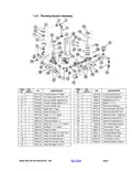
- Page 7: Plumbing system assembly includes various components and their specifications. Key items include vacuum breakers, pan head screws, and ball valves. Repair kits for vacuum breakers and ball valves are listed. Final rinse plumbing components are specified, including nipples and strainers. Water solenoid valves and their repair kits are included in the assembly. Pressure regulators and gauges are part of the plumbing system. Thermometers for wash and rinse applications are mentioned. Brackets and nuts for plumbing support are also listed. The document references the model CMA-180 parts manual. It includes a section for purchasing parts.
- Page 8: Wash spray system components include various items such as manifolds, bolts, and spray arms. Key components listed include nylon lock nuts, hex head bolts, and spray base assemblies. Specific part numbers are provided for each item, indicating their descriptions and quantities required. The document references the model CMA-180 parts manual, indicating it is a revision. Additional details include the inclusion of certain items in specific part numbers. The page outlines the necessary components for the wash spray system assembly. It includes information on spray arm end plugs, gaskets, and washers. The document serves as a parts manual for the specified model. It emphasizes the importance of each component in the assembly process. The layout provides a clear structure for identifying and ordering parts.
- Page 9: Final rinse system components include various items such as vacuum breakers, elbows, gaskets, and plumbing parts. Key components listed are the vacuum breaker, final rinse elbow assembly, and inlet booster heater plumbing. Additional items include brass plugs, tees, fittings, and various screws and bolts. Specific parts like the rinse arm with bearing and mixing chamber are also mentioned. Instructions indicate that certain components may vary based on the machine model, particularly regarding the booster heater. The document references a parts manual for model CMA-180, indicating it is a revision. The list includes part numbers and descriptions for easy identification of required components. Overall, the document serves as a guide for assembling or repairing the final rinse system. It emphasizes the importance of using the correct parts for optimal functionality. The page is structured to provide a clear overview of necessary items for the final rinse system.
- Page 10: CMA-180 door handle assembly includes various components. Key components include door handle, door handle spacers, and door handle support. The assembly requires specific part numbers for each item. Included are items such as door spring extension rod and door roller switch. The manual lists required quantities for each part. Additional components include hex head bolts and cotter pins. The document is a parts manual for the CMA-180 model. It provides a revision number for reference. The page indicates a section for purchasing parts. This is page 10 of the manual.
- Page 11: Corner door handle assembly includes various components such as door handles, spacers, bolts, and brackets. Key components listed include door handle, door handle spacer (St), door handle spacer (Lg), and various types of bolts and washers. Specific part numbers are provided for each item, indicating their unique identifiers. The assembly includes items like door spring extension, door spring, and door handle cap. Additional components include limit switch door bracket and door panel corner. The document references a model, CMA-180, and indicates it is a parts manual. There are instructions for purchasing parts. The page is part of a larger manual, as indicated by the page number. The document revision is noted as Rev. 2.09. The assembly is detailed with required quantities for each part.
- Page 12: Pump system assembly includes various components and specifications. Key components include pump motors with different voltage options. The assembly requires specific bolts, studs, and seal kits. Additional parts include slip joint nut gaskets and compression nuts. The document lists various sizes and types of bolts and washers. It specifies the inclusion of a pump cover and impeller assembly. The parts manual is for model CMA-180 and is labeled as revision 2.09. There is a section for purchasing parts. The assembly includes a total of 15 items with specific part numbers. The document outlines the required quantities for each item.
- Page 13: Old wash tank heater (square flange) Wash tank heater 5KW 3PH Wash tank heater 7KW 3PH Heater thermostat Liquid level switch Liquid level switch shield Hi-limit switch - wash 250 degrees 7/8” probe hole plug Wash tank heater gasket Model CMA-180 parts manual Rev. 2.09
- Page 14: Booster heater (square flange) Booster tank Nylon lock nut 5/6”-18 Washer SS 5/16” Immersion heater 12KW 3PH Thermostat 12KW heater Hi-limit switch-booster 250 degrees Booster heater shield Booster heater gasket Complete assembly
- Page 15: Wash tank heater (triangular flange) Heater 6kW 220V triangular flange Heater 6kW 480V triangular flange Thermostat Liquid level switch Liquid level switch shield Hi-limit switch - wash 250 degrees 7/8” probe hole plug Gasket for triangular flange heater Model CMA-180 parts manual Rev. 2.09
- Page 16: New booster heater (triangular flange) Booster tank Nylon lock nut 5/6”-18 240V 12KW triangular immersion heater 480V 12 kW triangular immersion heater Thermostat 12KW heater Hi-limit switch-booster 250 degrees Booster heater shield Gasket for triangular flange heater Complete assembly
- Page 17: 480 control box assembly Transformer box Fuse holder - inline Fuse 1.25 amp 230V slow blow Fuse 1.50 amp 600V slow blow Fuse clip 2-poll, pressure plate Transformer box lid 10-32 3/8 truss head screw Model CMA-180 parts manual Rev. 2.09 Buy parts
- Page 18: Control Box Assembly CMA-180 Control Box Body Toggle Switch Rubber Boot Timer CMA-180 60 Amp Terminal Block-Green Counter Face Mount 220V Motor Contactor 208/240V 20A Control Box Sponge Long Control Panel Label CMA-180 Model CMA-180 Parts Manual Rev. 2.09
- Page 19: Control box assembly CMA-180 control box body Timer CMA-180 60 amp terminal block-green Counter face mount 220V Motor contactor 208/240V 20A Control box sponge long Control panel label CMA-180 Includes timer motor p/n 501.17 and microswitch 411.00 Only for the machines with booster heater
- Page 20: Unique parts for CMA-180TS include various items such as door guides, pump covers, and scullery doors. The document lists specific part numbers and descriptions for each item required. Key components include the pump base, impeller, and various door handles. Additional items include support brackets and a final rinse manifold. The document is part of the CMA-180 parts manual, indicating it is a resource for obtaining replacement parts.
- Page 21: Unique parts for CMA-180TC include various components such as door panels, guides, and pump parts. The document lists required items and their part numbers. Key components include the scullery door, manifold, and pump cover. Additional items include door handles, limit switch brackets, and transfer hoses. The manual is identified as the CMA-180 parts manual, revision 2.09. There is a section for purchasing parts.
- Page 22: Unique parts for CMA-180T split door include various components such as door safety brackets, open door latch, and door stops. The document lists item numbers, part numbers, and descriptions for each component. Key components include left and right door safety brackets, wrapper, door spring, and door extension link. The model referenced is CMA-180, and the document is identified as the parts manual, revision 2.09.
- Page 23: Power switch bulb replacement instructions Note: For old style machines only - manufactured prior to May 2002 To replace bulb Using a 5mm-screw driver, dismount the light module from the actuator as shown in illustration 1 & 2. Replace the burnt bulb with a new one P/N 17421.10 by twisting the bulb 90 degrees. Mount the light module by snapping it onto the actuator as shown in illustration 3.
- Page 24: 180 Conversion Kit – Corner to Straight #00617.18 Open dishmachine doors to their highest position to reduce spring resistance on the door handle. Remove hardware holding the door handle to the door linkage and save all washers and spacers. To remove the door handle, unscrew the four bolts holding the door handle mounting plates. Remove door panel & hardware from the left side of the machine and install door guides from the kit. Using provided nuts, bolts, and washers, mount the left and right door handle supports on the back of the cabinet. Swing the door handle downwards to reach the door linkages and attach them using the provided bolts. Eyebolt adjustment nuts should be adjusted to the point the doors begin to lift from a closed position. Illustration #2 shows CMA 180-S and CMA 180-C door handle assembly.
- Page 25: Conversion kit – straight to corner instructions. Open the dishmachine door to its highest position to reduce spring resistance. Remove hardware holding the door handle to the door linkage and save all washers and spacers. Swing the door handle towards the back and dismount it from the support brackets. Remove the two door-handle support brackets and plug the holes with original hardware. Replace the front door with the left door and relocate the service door splashguard. Install the door handle using provided mounting plates, bolts, nuts, and washers. Attach the extension rod to the back of the door handle and connect the spring. Adjust the nut on the eyebolt until the doors begin to lift, then back off two turns. Illustrations provide guidance for proper location of all door handle hardware.

LG LDPS6762D PrintProof Black Smart Dishwasher

BOSCH SMV4HCX52E-39 Dishwasher

Whirlpool WFE2B19X Dishwasher

FISHER PAYKEL DD60ST4HNB9 Built Under Dishwasher

SIEMENS SN93E805CE Fully Integrated Dishwasher

SIEMENS SX73HX10VG Dishwasher

Miele PFD 104 SCVi XXL XXL Dishwasher

BOSCH SMV6HCX3FR Dishwasher

Electrolux ESZ89400UX 800 SprayZone Dishwasher

BOSCH SHE53CM2N Recessed Handle Dishwasher