Home > CMA Dishmachines > CMA DISHMACHINES CMA-180VL Dishwasher
CMA DISHMACHINES CMA-180VL Dishwasher


Owner’s Manual
MODEL CMA-180VL/180VL Tall
Installation and Operation
Manual
Rev 2.01C 09-2024
CMA DISHMACHINES
17707 VALLEY VIEW AVE
CERRITOS, CA 90703
8 0 0 - 8 5 4 - 6 4 1 7
FAX 714-895-2141

| General | Details |
|---|---|
| Name | CMA DISHMACHINES CMA-180VL Dishwasher |
| Make | CMA Dishmachines |
| Language | English |
| Filetype | PDF (Download) |
| File size | 0.74 MB |


CMA DISHMACHINES EST-44 Conveyor Dishwasher

CMA DISHMACHINES CMA-180UC Under Counter Dishwasher

CMA DISHMACHINES EST-AH Door Type Rack Low Dishwasher

CMA DISHMACHINES UC65e M3 Dishwasher

CMA DISHMACHINES UC50e Dishwasher

CMA DISHMACHINES CMA-180 Dishwasher

CMA DISHMACHINES CMA-180UC Dishwasher

CMA DISHMACHINES H-1X Undercounter Dishwasher

CMA DISHMACHINES 180UC-3 Under Counter Dishwasher

CMA DISHMACHINES AH Straight Thru Design Dishwasher

CMA DISHMACHINES CMA-180VL Dishwasher Overview
Summary of Contents
- Page 1: Owner’s Manual Model CMA-180VL/180VL Tall Installation and Operation Manual
- Page 2: Model CMA-180VL Specifications Getting started Introduction to CMA-180VL Receiving and installation Electrical requirements Plumbing Chemical dispensers Installation checklist Machine start-up procedures
- Page 3: Electrical ratings include volts, phase, and amps for various configurations. The required flowing water pressure for the dishwasher is 15-65 PSIG. A pressure regulating valve must be installed if pressures exceed 65 PSIG. Improper machine operation may result if flowing pressure is lower than 15 psi. Model CMA-180VL installation and operation instructions are provided. Shipping weight is indicated as 332#. The document is a revision labeled 2.01C. The page number is 4.
- Page 4: Getting started The CMA-180VL is a hot water sanitizing, single rack, door-type dishmachine. It features a self-contained booster heater and requires only power supply, water supplies, drainpipe, and chemical dispensers. The machine utilizes recirculated wash water and fresh water final rinse. It is equipped with a built-in Heat Recovery System that reduces humidity in the dishwashing room. The manual provides a complete reference guide to the CMA-180VL, structured for user comprehension. Instructions for unpacking, installation, and setup are included in the manual. Requirements for plumbing, wiring, and space considerations are outlined. The operation section offers easy-to-understand instructions for all levels of operators. CMA recommends utilizing a water softening system to maintain optimal water hardness. CMA disclaims warranties for installations not following the provided instructions exactly.
- Page 5: Plumbing The building's ambient or cold tap water is supplied to the dishwasher through the cold water inlet valve located at the bottom of the dishwasher. The steam and heat rising from the wash cabinet is used to preheat the incoming water to 130 to 140 degrees. The booster heater boosts the final-rinse water temperature to 180 to 190 degrees for proper sanitizing. At the end of the wash cycle, a steam evacuation cycle will begin. Once the steam evacuation cycle is completed, the operation indication light will turn off. The hot water source is used to fill the dishwasher with hot water needed for the wash tank. Cleaning of the condenser is done at the end of the day or after each service when the main power switch is turned off.
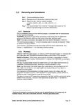
- Page 6: Receiving and installation steps include removing packaging material and the service manual from inside the wash tank. Adjust the feet and set the machine in place, ensuring it is level side-to-side and front-to-back. Maintain a distance of at least eight inches between the table scrap sink and the dishmachine. Ensure the electrical supply is compatible with the specifications on the machine's data plate. Electrical and grounding connections must comply with the National Electrical Code and local electrical codes. Use copper wire rated at 90 degrees C minimum for supply connections. The machine can handle both single and three-phase applications. For plumbing, a minimum 140°F hot water supply and a minimum 41°F cold water supply are required. The plumber must flush the water lines thoroughly before connecting to the dishwasher. High iron and chlorine levels in the water supply may require additional filtration systems.
- Page 7: Chemical dispensers must be operated with an automatic detergent feeder and, if applicable, an automatic chemical sanitizer feeder. There should be a visual means to verify that detergents and sanitizers are delivered or an alarm to signal if they are not available. Check valves should be installed directly at the mixing chamber coupling located by the vacuum breaker on the back of the machine. There are two 1/8” FPT mounting holes provided on the mixing chamber coupling for check valves. Only one hole is needed with the high temp machines for rinse chemical only. Remove the plugs from the mixing chamber and install injection fittings supplied with your dispenser. A 7/8” detergent injection hole is provided in the back of the wash tank. Use only commercial-grade detergents and rinse aids recommended by your chemical professional. Low temperature chemical-sanitizing dishmachines must not exceed 6% sodium hypochlorite solution as the sanitizing agent. Electrical and plumbing connections must be made by qualified persons who comply with all applicable codes.
- Page 8: Straight to corner operation retrofit instructions. To convert the machine from straight to corner application, relocate the tray track rail from straight to corner position. Mount the tray track using the same bolts, washers, and lock nuts used for straight application. MODEL CMA-180VL INSTALLATION & OPERATION Rev. 2.01C
- Page 9: Tempering kit (optional) Model CMA-180VL installation & operation
- Page 10: Installation checklist includes checking for concealed damage, ensuring hot and cold water supply temperatures, verifying incoming water supply lines and flow pressure, and confirming proper circuit breaker sizing. The dishmachine must be properly ventilated with a minimum clearance for the fan and have plumbing installed with an air gap that meets local codes. It is essential to ensure the dishmachine is grounded, leveled, and that dishrack guides are adjusted to the level of the dishtable. Water hardness should not exceed 3 grains, and the Ventless feature must be operating correctly. Start-up procedures involve placing scrap baskets, securing wash and rinse arms, and selecting the appropriate toggle switch position on the control panel. Rinse pressure should be adjusted using the regulator and gauge, and the power switch must be turned to the on position. The detergent and rinse dispenser need to be connected to the power block inside the control panel. Installation of the rinse injection fitting and the chemical probe hole in the wash tank is also required.
- Page 11: A 7/8” detergent fitting hole is provided in the wash tank behind the machine. Check the machine operating temperatures. The wash temperature must be 155°F minimum. The rinse temperature must be 180°F minimum. Adjust the temperatures by removing the panel in front of the respective heater and turning the adjustment stem clockwise to increase. Rinse water temperature must be observed during the rinse cycle. Check all water and drain fittings for leaks. Install the wall chart and instruct the machine operator on the proper cleaning and operation of the CMA-180VL. The flush-down or cleaning of the condenser is done when the main power switch is turned to the off position. Booster heater is shipped on the dishmachine empty to prevent freezing. When initially filling a newly installed dishmachine, you must fill the booster tank prior to connecting the removed wire. The Door Safety Interlock (DSI) is used to prevent the wash cabinet doors from being opened while the dishwasher is in operation.
- Page 12: Electrical requirements for the CMA-180VL include standard factory wiring for 3-phase operation. It is important to check the electrical data plate for confirmation. Proper wiring instructions for both rectangular and triangular booster and wash heaters are provided in the figures. The wiring diagram is essential for correctly wiring the terminal power block, tank heater, and booster heater for single-phase operation. Refer to the Wiring options section for details on 1-phase power supply.
- Page 13: Wiring options include 3-phase and 1-phase configurations. Power signal is 208/230 volts, with the power block labeled inside the control box. Conduit holes for detergent and rinse are provided on the control box. A threaded injection point is available on the final rinse Teflon mixing chamber. A hole is provided in the tank for probe access, located on the front side of the wash tank. Refer to the machine data plate for power connection options. Electrical requirements vary for machines with or without a booster heater. Ensure the machine is properly grounded to comply with local and national codes. Install power supply wires to the appropriate terminals on the power block. The high or wild leg must be connected to the L2 terminal if applicable.
- Page 14: Quick service guide Model: CMA 180 VL high temp Door mechanical switch problem Align switch Replace switch Loose wire connections Check and crimp connectors Pump motor not running Replace wash pump motor Faulty high limit switch Adjust thermostat
- Page 15: Initial parts kit P/N 1100.17 includes various components necessary for the CMA-180VL model. The kit contains essential parts such as the pump assembly, pump seal kit, and various gaskets and arms. It is recommended to keep this initial parts kit on hand as a backup supply for emergency service. All parts in the kit are unique to the CMA-180VL dishmachine. These components are crucial for the quality operation and customer service of the CMA-180VL unit. The document is part of the model CMA-180VL installation and operation manual. The page is labeled as Rev. 2.01C.
- Page 16: Auto-fill solid state timer allows for a pre-selected delay period that can be adjusted. The adjustment is made by turning dip switches on for the proper time setting. Removal of input power will reset the control. The document references the model CMA-180VL. It includes installation and operation instructions. The revision of the document is 2.01C. The page number is 17.
- Page 17: Wire diagram for CMA-180VL 240V. Addition of energy saver relay will allow wash tank heater element to shut down after set time of machine non-operation for all CMA 180 dish machines. Models include 180 HTSB, 180 HTCB, 180 T-HTSB, 180 T-HTCB, 180-VL, and 180T-VL. Model CMA-180VL installation and operation. Rev. 2.01C.
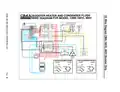
- Page 18: Wire diagram for model: CMA-180 VL with optional door safety interlock (DSI). Power switch. DSI solenoid. Cycle light. Rinse solenoid valve. Auto-fill switch. Delime off counter. Door safety switch. Thermostat. Wash tank heater.
- Page 19: Booster heater and condenser flush Wire diagram for model: CMA-180VL Condenser flush Condenser flush valve Rinse signal Detergent Hi limit switch Adjustable thermostat Wash tank heater Pump motor
- Page 20: Wire diagram for model CMA-180VL 480V. Power switch. Optional auto-fill switch. Cycle light. Optional auto-fill valve. Rinse solenoid valve. DSI solenoid. Delime off counter. Normal door safety switch. Wash tank heater pump motor.
- Page 21: Booster heater and condenser flush Wire diagram for model: CMA-180VL 480V Condenser flush Rinse signal Detergent Hi limit switch Wash tank heater Adjustable thermostat Pump motor 6 kW heater wiring options

FISHER PAYKEL DD60SCTX9 Single Dishwasher

FISHER PAYKEL DD24SCTB9N Sanitize Tall Dishwasher

BOSCH SMS4EVI04E Dishwasher

smeg DI13M2 Dishwasher

AEG FSK94858P Dishwasher

Hotpoint H7F HS51 Dishwasher

BOSCH SMS4HKI00G Dishwasher

Hisense HS622E90BUK Dishwasher

newWORLD NW60DWFSW Full Size 15 Place Dishwasher

BOSCH SPV4HKX53E 4 Total Dishwasher