Home > CMA Dishmachines > CMA DISHMACHINES CMA-180UC Under Counter Dishwasher
CMA DISHMACHINES CMA-180UC Under Counter Dishwasher


Owner’s Manual
MODEL CMA-180UC
INSTALLATION & OPERATION
Rev 1.20 03-01-2022
C M A D I S H M A C H I N E S
1 2 7 0 0 K N O T T S T R E E T
GARDEN GROVE, CALIFORNIA 92841
8 0 0 - 8 5 4 - 6 4 1 7
FAX 714-895-2141

| General | Details |
|---|---|
| Name | CMA DISHMACHINES CMA-180UC Under Counter Dishwasher |
| Make | CMA Dishmachines |
| Language | English |
| Filetype | PDF (Download) |
| File size | 1.46 MB |


CMA DISHMACHINES EST-44 Conveyor Dishwasher

CMA DISHMACHINES EST-AH Door Type Rack Low Dishwasher

CMA DISHMACHINES UC65e M3 Dishwasher

CMA DISHMACHINES CMA-180VL Dishwasher

CMA DISHMACHINES UC50e Dishwasher

CMA DISHMACHINES CMA-180 Dishwasher

CMA DISHMACHINES CMA-180UC Dishwasher

CMA DISHMACHINES H-1X Undercounter Dishwasher

CMA DISHMACHINES 180UC-3 Under Counter Dishwasher

CMA DISHMACHINES AH Straight Thru Design Dishwasher

CMA DISHMACHINES CMA-180UC Under Counter Dishwasher Overview
Summary of Contents
- Page 1: Owner’s manual Model CMA-180UC Installation & operation Rev 1. 20 03-01-2022 CMA dish machines
- Page 2: Model CMA-180UC Specifications CMA-180UC operational cycle Getting started Introduction to CMA-180UC Receiving and installation Electrical Plumbing Detergent and rinse chemical dispenser (optional) Operating and cleaning instructions Troubleshooting
- Page 3: Specifications Water consumption per rack: 0.75 gal (2.83 L) Operating cycle: Wash time - 94 sec, Rinse time - 16 sec, Dwell time - 10 sec Operating capacity: Racks per hour - 30 Wash tank capacity: 2.5 gal Required minimum temperature: 120°F (49°C) Recommended temperature: 140°F Rinse pressure set: 20 PSI ± 5 PSI Cycle temperatures: Wash - 150°F - 160°F, Rinse - 180°F - 195°F Electrical rating: 208 volts, 1 PH - 60 Hz Shipping weight: 234 lbs (106 kg)
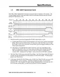
- Page 4: CMA-180UC Operational Cycle has a total cycle time of 2 minutes (120 seconds). The timing diagram details the individual functions executed during each operational cycle. Toggling the START switch begins a cycle, energizing both the Cam Timer motor and the Instant Start Relay. The Instant Start Relay latches ON the power to the Cam Timer motor, allowing the START switch to be released. After about 1.5 seconds, the Cam Timer’s first cam latches ON the power to the Cam Timer motor. The Cam Timer motor continues to run for a total of 2 minutes before switching OFF and resetting. The Cam Timer’s third cam controls the Wash Pump, which comes ON about 3 seconds into the cycle and runs for 94 seconds. The fourth cam powers ON the Drain Pump, running for about 7 seconds before powering OFF. This cam turns ON again midway through the Rinse Cycle and stays ON for 10 seconds. The Drain Pump turns OFF 2 seconds after the Rinse Cycle has completed.
- Page 5: About 3 seconds after the wash cycle has completed, the cam timer’s second cam controls the rinse cycle and stays on for 16 seconds. This 16-second period is the rinse cycle. The “Safe-T-Temp” fifth micro switch will pause the cam timer assembly if the booster heater has not reached 180 degrees. The machine will remain in wash cycle mode until the 180-degree rinse temperature is reached. At this time, the cam timer will advance automatically into the rinse cycle and dispense 180 degrees rinse water over the dishes. Cam switches 6 and 7 control the detergent and rinse pumps respectively. They turn on at the beginning of the wash and rinse cycle respectively and run for a few seconds to provide sufficient detergent and rinse additive. These cams can be adjusted as necessary for proper chemical dosage. Use only commercial-grade detergents and rinse additives recommended by your chemical professional. Do not use detergents and rinse additives formulated for residential dishwashers. Refer to section 4.1.1 for cam adjustment.
- Page 6: Getting Started Introduction to CMA-180UC This manual is structured to provide a complete reference guide to the CMA-180UC. The CMA-180UC is a hot water sanitizing, single rack, under-counter dishmachine. It is a standalone machine featuring a self-contained booster heater. Operation of the CMA-180UC is extremely user friendly. The machine retains the features of the standard CMA-180 Series in that it has a scrap tray. The first section explains how the machine is packaged and what to look for when receiving the machine. Requirements are given for plumbing, wiring, and space considerations. The function of the machine itself is mostly automatic and takes little training to put into full operation. CMA expressly disclaims any and all warranties relating to the installation of any CMA equipment.
- Page 7: Getting started The dishwasher is shipped from the factory in a corrugated box on a wooden pallet. Installation guidelines provide a systematic procedure for setting up the machine. Start by removing the packaging material. The wash tank scrap screen must be in place during operation. It strains water circulating through the spray arms and pump assembly. Set the machine in place and level it to prevent door leaks. Wood and laminates are unsuitable for areas exposed to dishwasher steam. Electrical supply must be compatible with the machine's specifications. The supply water to the dishwasher must be a minimum of 120°F with a 4 GPM flow rate. All electrical and plumbing connections must be made by a qualified person.
- Page 8: Getting Started Warning: If water pressure exceeds 50 PSI, a pressure reducing valve (PRV) is recommended. The CMA-180UC is supplied with a drain pump for elevated drains. For floor gravity drain applications, the drain pump should not be used. If removing a drain pump, safe-end the white and purple wires and secure them out of the way. If a drain pump is used with a floor drain, the drain hose must rise 12 to 16 inches before dropping to the floor drain. Caution: CMA recommends utilizing a water softening system to maintain water hardness measurements of 3.5 gpg or less. This will assure maximum results and optimum operation of the dishmachine. Optional built-in chemical dispenser assembly has easy access for chemical settings behind the front kick panel. Basic settings for both detergent and rinse speed are 50%. Use only commercial-grade detergents and rinse aids recommended by your chemical professional.
- Page 9: Getting Started The NOVA detergent and rinse dispenser has its own reference manual. Familiarize yourself with the dispenser’s reference manual before proceeding with installation. The NOVA dispenser is pre-wired with a multi-conductor electrical cable that is to be run through a conduit to the power block inside the control panel drawer. Use a ½” watertight conduit meeting all local and national codes. A conduit fitting is present on the bottom of the dispenser where the power cable exits. Run your dispenser wires through the conduit and through the enclosed area across the top of the machine. With the machine’s power “OFF”, connect your detergent and rinse dispenser wires to the power block supplied and labeled inside the control panel drawer. The table that follows lists the function of each conductor of the multi-conductor electrical cable. All electrical and plumbing connections must be made by a qualified person who will comply with all available Federal, State, and Local Health, Electrical, Plumbing and Safety codes.
- Page 10: Getting started Brown (LIVE) wire Multi-conductor cable Rinse signal wires Detergent signal wires Black (Main Power) Gray/Violet (Main Power Neutral) Machine neutral (White wires) Remove the plug from the mixing chamber located by the vacuum breaker on the back of the machine. The final step of installing the CMA supplied detergent and rinse dispenser is programming it to your specific application.
- Page 11: Getting started The CMA “Safe-T-Temp” feature assures the final rinse cycle is always at a consistent minimum of 180 degrees. The “Safe-T-Temp” function operates off the 5th cam on the timer assembly. The cam timer assembly pauses if the booster heater is still heating. The machine remains in wash cycle mode until the rinse temperature is met. At this time, the cam timer will advance automatically into the rinse cycle. If the Safe-T-Temp cam is not used, it becomes a spare cam. Installation instructions include removing the 4 cam timer assembly and installing the 5 cam timer. All wires removed from the 4 cam timer assembly must be placed in the exact position on the 5 cam timer assembly. The “Safe-T-Temp” 5 cam timer assembly kit includes specific wiring instructions for connections. Connect the white wire with male bullet connector from the kit to the dishmachine harness.
- Page 12: Getting started Drain water tempering kit Model CMA-180UC installation & operation manual Rev. 1.20
- Page 13: Getting Started Booster heater must be filled with water prior to connecting the blue wire from the high limit switch. The high limit switch can be found by removing the front panel and locating the red button on the front of the heater tank. The thermostat should be adjusted to maintain 180°F during the final rinse cycle. The booster tank must be filled with water before the heating element is energized. The “High Limit Switch” has intentionally been disconnected at the factory and will require re-connection before the heating element will turn on. Close the door on the machine. Turn the power switch to the ON position. On initial setup, push the Booster Fill button to fill the booster heater. The machine will be automatically filled to the correct level. Dishmachine checked for concealed damage.
- Page 14: Operation Initial Setup The CMA-180UC requires a supply water input pressure of 24 PSI minimum. Use the following procedure to adjust the rinse pressure to 20 PSI. Machines built prior to January 2020 will be automatically filled to the correct level. Machines built after January 2020 press and hold the FILL button for 25 seconds. The rinse temperature must be 180°F minimum. If necessary, adjust the temperatures by removing the front kick panel and turning the thermostat adjustment. Install wall chart and instruct machine operator on proper cleaning and operation of the CMA-180UC. Startup Procedures Open the door of the machine and check that the scrap screen is in place. Press the rocker switch marked “START” – the machine will automatically begin its cycle.
- Page 15: Operation At the end of the wash period, drain the machine by pressing and holding the rocker switch marked “DRAIN”. Clean the wash tank screen and scrap tray screen. Remove and clean the spray arms. To prime chemical dispensers press and hold down prime switch until product is discharged into dishmachine.
- Page 16: Operating and cleaning instructions for model CMA-180UC. Start the machine by pushing the start button. Turn on power, press and hold the fill button for 25 seconds. Caution: Do not start until wash temperature reads 150°F. If spray arms are clogged, remove by turning bearings counterclockwise. Drain the machine by pressing the drain button. Hand remove and thoroughly clean filter, scrap screen, and inspect top and bottom spray arm jets daily. Use a toothpick to push trash into the spray arm. Remove end plugs and flush with water. Replace all screens back into position.
- Page 17: Operating and cleaning instructions. Model CMA-180UC installation and operation manual.
- Page 18: Preventive maintenance chart Model CMA-180UC installation & operation manual
- Page 19: Quick service guide Model: CMA 180UC high temp under counter Technical issue: Scrap trap overflows Cause: Pressure regulator is not set properly Solution: Set regulator to 15-25 psi Faulty rinse micro switch Solution: Replace micro switch, P/N 00411.00 Drain hose elevated too high Solution: Must be lowered to goose neck level Obstruction in drain hose Solution: Check hose & clean, clean exit screen Faulty drain pump Solution: Replace pump, P/N 15503.00 Machine not level Solution: Adjust machine legs to level Door leaks Solution: Replace gasket, P/N 14506.60 Thermometer failure Solution: Correct, replace, P/N 03202.66
- Page 20: Operation Troubleshooting Machine inoperative - Power off at circuit breaker - Defective power switch Motor inoperative - Door is open - Control panel is pulled out - Defective reed switch Heater (no heat) - Defective reed switch - High limit switch opened or defective - Defective thermostat Heater (never turns off) - Defective thermostat - Defective heater contactor
- Page 21: Operation Low heat during operation - Low incoming water temperature (below 140° F) - Thermostat out of adjustment - Cold water mixing with supply - Defective heater Low rinse water pressure - Pressure regulator out of adjustment - Defective pressure gauge - Insufficient water supply flow - Defective water solenoid valve Low rinse water flow - No rinse water flow - Limed up rinse arm spray nozzles - Defective water solenoid valve - Defective rinse relay Water overflows scrap tray - Drain hose is kinked - Drain hose is not properly elevated - Defective timer assembly - Defective drain pump With power on, activating start switch does not begin cycle - Defective start switch - Defective timer assembly
- Page 22: Operation Start switch requires > 3 second activation to run cycle. Pressing and holding fill switch does not fill machine. Fill (rinse water) won’t shut off. Pressing and holding drain switch does not drain machine. Cycle light does not light while cycle runs. Power light does not light but machine runs. Wash tank or final rinse temperature does not display. Both the wash tank temperature and the final rinse temperature do not display. Wash tank or final rinse displays wrong temperature. MODEL CMA-180UC INSTALLATION & OPERATION MANUAL Rev. 1.20
- Page 23: Operation Parts Kit Initial Parts Kit (P/N 1100.66) Motor contactor, 2-pole 20 amp Heater contactor, 2-pole 35 amp 2-minute timer motor Ice cube relay 120 V ½ water solenoid repair kit JE Rocker switch start momentary Rocker switch drain/fill Dual temperature display kit
- Page 24: Operation Drain pump Drain motor Ultra Jet for CMA-180UC Twist tie Hose clamp 1” Drain line gooseneck 10-32 SS nut Black drain hose 1 ID x 3 1/2 Drain hose with goose neck Rubber hose 90 deg.
- Page 25: Operation Drain pump removal instructions Drain pump should only be used if a floor drain is not accessible to the machine at installation. When converting the UC-180 dishwasher to a gravity drain unit, remove the drain pump assembly. Re-route the 6ft drain hose to the center port where the drain pump was located. Ensure there is a 1” air gap between the discharge and floor drain. Disconnect the wires. Remove the hose clamp over the drain valve. Remove drain hose from the drain gooseneck. Disconnect the 3-inch pump inlet drain hose.
- Page 26: Operation Customer notice Improper installation of this product may void the warranty on this machine. Please follow these guidelines for recommended installation and to ensure the warranty of this model is authorized by CMA Dishmachines. Dishmachine installation requirements Machine must be level. Adjust leveling feet to accommodate uneven floor surfaces. Stand pipe drain height should not exceed maximum height of 22”. If there is a floor drain, it is highly recommended the pump drain be removed. Approximately 4-feet of ¾” flexible conduit with power leads are provided for easily connecting the power at installation. CMA recommends a minimum 50-amp dedicated circuit, but you should consult your local building code requirements for proper breaker size. Activating/adjusting the booster heater Booster heater must be filled with water prior to connecting the blue wire from high limit switch. Once the booster has been connected, the thermostat should be adjusted to maintain 180°F during the final rinse cycle. Automatic dispensing equipment Applications utilizing automated dispensers for administering warewash chemicals must use 110v dispenser equipment.
- Page 27: Electrical diagrams Model CMA-180UC installation & operation manual
- Page 28: There is no text on the page to extract.
- Page 29: There is no text on the page to extract.
- Page 30: - Electrical diagrams are included in the document. - The effective date range is from January 2018 to January 2020. - The document is the installation and operation manual for model CMA-180UC. - The revision number of the manual is 1.20.
- Page 31: Electrical diagrams effective January 2020. Drain pump. Cam timer N.O. Detergent. Rinse. Fill. Neutral. Run signal. Start switch. Drain switch.
- Page 32: CMA-180 UC electrical diagram Control panel Digital thermometer Transformer Temperature sensors Rinse relay Start relay Door safety switch Detergent Start switch

Whirlpool W2F HD624 Dishwasher

BOSCH SHX65CM5N Dishwasher

BOSCH SMV4HTX00E Dishwasher

FISHER AND PAYKEL DD24STI9 Dishwasher

Smeg LSPU8653X Dishwasher

BOSCH SHP78CM6N Dishwasher

SIEMENS SN43HW32US Dishwasher

BOSCH SMD6YCX02E Available Customer Service Dishwasher

FISHER AND PAYKEL DD24SI9 Dishwasher

Indesit D2F HD624 A Separate Dishwasher