Home > Centerline > Centerline CDH ML-130374 Commercial Dishwasher
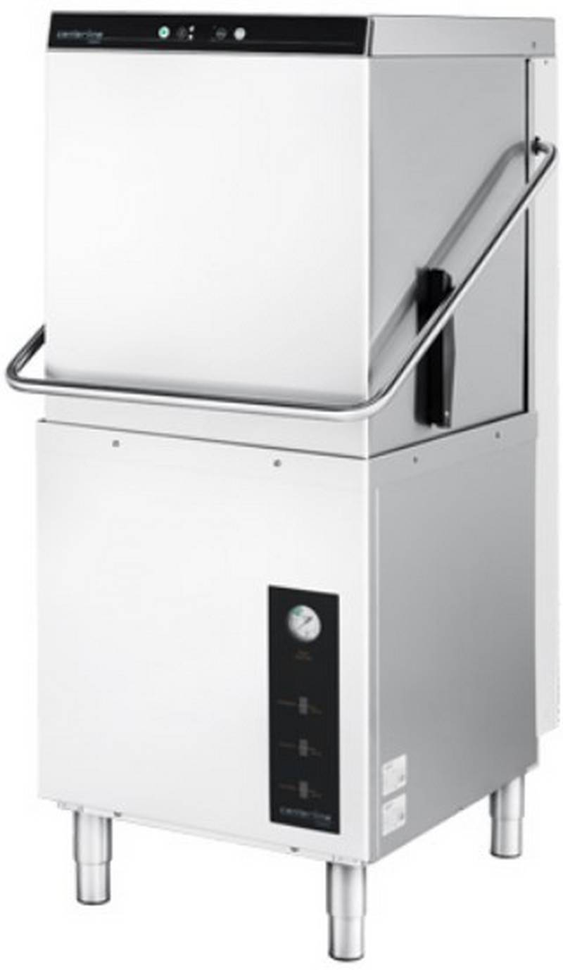
Centerline CDH ML-130374 Commercial Dishwasher


Centerline Models
Ecoline Models
CDH
CDL
ML-130374
ML-130375
EDH
EDL
ML-130379
ML-130380
Commercial Dishwasher
Installation and Operation Manual
0F-041220
August 2022
Ver2.0

| General | Details |
|---|---|
| Name | Centerline CDH ML-130374 Commercial Dishwasher |
| Make | Centerline |
| Language | English |
| Filetype | PDF (Download) |
| File size | 1 MB |


Centerline CUH-130363 Commercial Dishwasher
centerline CDH-1 51 Racks Hour Door Type Dishwasher

Centerline CDH ML-130374 Commercial Dishwasher Overview
Summary of Contents
- Page 1: Centerline models Ecoline models Commercial dishwasher Installation and operation manual
- Page 2: Machine installation checklist Machine serial number Machine contents verified Peg rack Combination flat rack Literature pack 3Ph to 1Ph conversion pack Small parts pack Machine legs installed and leveled Water hookup
- Page 3: Installation and operation manual Table of contents Notes on the documentation Application Layout of the documentation Representative convention Symbols used Safety instructions and regulations Safety instructions and warning notices Product description Intended purpose Controls
- Page 4: Installation and operation manual Connecting the water Water requirements Water connection Connecting the drain Venting requirements Rate of exhaust flow calculations Connecting to the power supply Electrical data Chemical supply set up
- Page 5: Installation and operation manual for CENTERLINE ECOLINE. Preparing the machine. Preparing the ware for washing. Washing. Extending wash time (CDH and CDL only). Daily cleaning or after each meal period. Weekly cleaning. Removing hard water deposits (Deliming). Overview of operator menu. Detergent dispensing (CDL, EDL and CDH, EDH with internal chemical pumps). Sanitizer dispensing (CDL and EDL machine only).
- Page 6: Installation and operation manual Aux channels Software version / machine program Display of errors and information Error Information Troubleshooting guide Poor wash results Other faults Maintenance Disposal
- Page 7: Notes on the documentation This document contains important information for the installation and startup of the machine by qualified personnel, as well as the information required for day-to-day operation by the operator. Keep the operating instructions and all referenced documents in a safe and accessible place. This Installation and Operations manual is subject to change. Referenced documents are all instructions that describe the installation, operation, maintenance, and repair of the device, as well as additional instructions for all accessories used. For the operator: Operating instructions For the qualified technician (available online): Installation instructions, Circuit diagram, Spare Parts Catalog Symbols used: Warning of hazardous electrical voltage, Beware of hazardous substances, Beware of hazard area, Useful additional information and tips.
- Page 8: CENTERLINE ECOLINE Installation and Operation Manual Important information on machine operation, not a warning notice. During machine operation, observe the general safety instructions and warning notices that precede each action. The hazard level is part of the safety instructions and is denoted by the signal word. Potentially hazardous situation can cause serious physical injury. Potentially harmful situation can cause damage to the product or other objects. Warning notices are depicted with warning symbols and signal word in the corresponding safety colors. The machine conforms to state-of-the-art technology and the recognized safety regulations. Operate the machine only if it is in good working order and in compliance with the operating instructions.
- Page 9: Installation and operation manual for CENTERLINE ECOLINE. Observe the regulations on occupational health and safety. Carefully read through the operation manual before use. Qualified electrician and plumber are required for installation/setup. Work on the electrical system should be done by a qualified electrician. Have the machine connected to the power supply by qualified personnel. Wear protective equipment when handling chemicals. Do not open the machine during operation; wait for the cycle to finish. Temperatures below 32°F (0°C) lead to functional damage. Before storing below 32°F (0°C), empty residual water in hoses, tank, and booster.
- Page 10: Product description The machine is intended solely for commercial dishwashing. The machine is designed for cleaning ware from the food industry. Models CDH, CDL, EDH, and EDL can be configured for straight through or corner operation. CDH and EDH dishwashers operate in high temperature sanitizing mode. CDL and EDL dishwashers operate in chemical sanitizing mode. The serial number is located on the machine data label. Hobart supplied chemical pumps ship standard with CDL and EDL models. The machine must be operated with an automatic detergent feeder. The wash pump motor has thermal overload protection. An automatic pumped drain is standard on all models.
- Page 11: Installation and operation manual for the CENTERLINE ECOLINE. A frame mounted 6.0kW electric booster water heater is equipped on the CDH and EDH high temperature sanitizing models. The booster water heater is designed to maintain a minimum final rinse temperature of 180°F provided the incoming water is at least 110°F. High-temperature models typically require a hood or vent over the dishwasher to meet local codes. Low-temperature chemical sanitizing machines or low usage electric heat dishwashers may not require individual venting of the machine if the room is amply exhausted. Refer to section 5.8 for venting and hood requirements. The rating label is located on the right side of the machine. If you have any questions regarding service and parts, use the serial number in all communications. Technical specifications include model dimensions and water consumption per cycle. The machine weight varies by model, with weights ranging from 191 lbs to 210 lbs.
- Page 12: Installation and operation manual Controls Power/drain button switches the machine on, fills and heats the wash tank. Pressing and holding activates self-cleaning cycle, drains machine, and switches off automatically. Start button begins the wash cycle; pressing within 10 seconds activates extended wash cycle. Menu button enters the configuration menu. Delime button initiates the deliming cycle. Temperature display shows wash tank temperature while idle or in a wash cycle. Temperature display for rinse shows temperature only during rinse cycle. Installation must only be carried out by qualified personnel. Risk of electric shock and fire hazard from water flowing over live components. Ensure the machine is correctly stored and does not overflow when being filled.
- Page 13: Installation and operation manual Frost damage Temperatures below 32°F (0°C) during transport/storage cause function impairments. Prior to installation, store machine at room temperature (min. 60°F / 15°C) for 24 hours. Transporting to the installation location Where possible transport packed on the pallet. Use suitable transport means (forklift or hand truck, etc.). Unpacking Remove packaging materials and accessories from the machine. Packaged in machine includes various components such as peg rack, combination flat rack, and literature pack. Installation and operations manual, programming card, operations and error card, operation and cleaning wall chart are included. Small parts pack includes chemical supply filters, nozzle cleaning tool, and machine legs.
- Page 14: Immediately after unpacking the dishwasher, check for possible shipping damage. If this machine is found to be damaged, save packaging materials and contact the carrier within 5 days of delivery. Use caution when using a forklift to remove the machine from the pallet. Do not use the door lift handle to move the machine, as it will cause door lift issues. Prior to installation, test the electrical supply to ensure it agrees with the specifications on the machine data label. Installation must be in accordance with state and local codes and the National Electrical Code ANSI/NFPA70 (latest edition). The machine is shipped without the legs attached. Install the provided legs in each of the bottom corners of the machine. The machine must be level to operate properly. Before finalizing the location, ensure consideration for electrical conduit, water supply, drain connection, and adequate clearance for opening the door.
- Page 15: Installation and operation manual for CENTERLINE™ ECOLINE™. The dish tables are fastened to the machine using included table support brackets. The support brackets mount underneath the tabling and fasten to the machine using M5 screws. Drill a locating hole and fasten using non-rusting ¼” screws and locking nuts. Attach the included splash guards at the rear of the tabling using non-rusting ¼” screws and locking nuts. For straight-through installations, 30 clearance at the front and 15 clearance at the right side must be provided for service. If the machine is being installed in a corner, clearances of 30 out from the dishwasher and 15” out from the dishwasher at the right side must be provided for servicing. The right corner of the machine should be positioned where the two tables meet for proper installation.
- Page 16: Installation and operation manual for wash tank and dish table. A splash shield kit is available for corner installations to prevent excessive splashing on the wall. Order sales accessory CORNER-INST-CD or service kit part number 00-563652. Refer to F-45915 installation instructions supplied with the kit for installation. A notch is required on both the front lip and the backsplash on the left tabling for corner installations. The left side splash guard is designed to be easily modified to fit the notch.
- Page 17: Installation and operation manual for CENTERLINE ECOLINE. For straight-through installations, position rack guides on the front and back side of the rack track aligning holes in the rack guide to spacers on the rack track. For corner installations, position rack guides on the left side and back side of the rack track aligning holes in the rack guide to spacers on the rack track. The machine must be operated with potable water. Proper water quality can improve ware washing performance by reducing spotting, enhancing effectiveness of labor, and extending equipment life. Recommended water hardness is 3 grains of hardness per gallon or less. Higher hardness may cause excessive formation of lime scale. Water hardness above 3 grains per gallon requires water treatment. Water treatment has been shown to reduce costs associated with machine cleaning, reduce deliming of the dishwasher, and reduce detergent usage in the dishwasher.
- Page 18: Water quality can affect the operation of the dishwasher. High iron levels may require an iron filter. High chloride levels can cause pitting and may need a chloride removal system. Sediment may require a particulate filter. Dissolved solids may necessitate water treatment such as a water softener or reverse osmosis system. A water hammer arrestor should be installed in the common water supply line. Water lines must be thoroughly flushed out before connecting to the dishwasher. Debris not removed can render plumbing components inoperative. A manual shutoff valve should be installed upstream of the fill hose. It is recommended to install a line strainer in the supply line.
- Page 19: Installation and operation manual for CENTERLINE ECOLINE. Flowing pressure specifications for different models are provided. Recommended flowing pressure is 15 psi to 65 psi (1 bar to 4.5 bar). Improper machine operation may result in issues. Pressure regulating valve is not supplied and may be needed. Pumped rinse system does not require a water pressure gauge. Normal flowing pressure for certain models is 15 psi to 25 psi (1 bar to 1.7 bar). A water pressure gauge is supplied for pressure rinse systems. The supply hose is 110 inches long and is shipped attached inside the machine. Instructions for removing the rear cover panel and side cover panel are included.
- Page 20: Installation and operation manual Uncoil the supply hose and route through the supplied bushing located on the back of the machine base. The bushing might need to be removed to be able to fit the supply hose nut through it. Replace the right side cover panel. Connect the end of the water supply hose (¾” garden hose thread) to the building shut off valve. Use care not to kink or cut the water supply hose. Any required extension must be made using a suitable pressure hose.
- Page 21: Installation and operation manual for CENTERLINE ECOLINE. A drain hose, 19mm inside diameter and 110” long, is provided with the machine. Plumbing connections must comply with applicable sanitary, safety, and plumbing codes. Remove the screws holding the rear cover panel top to the machine and lift off the panel. The door will need to be opened to remove the rear cover panel top. Remove the screws holding the rear cover panel to the machine and lift off the panel.
- Page 22: Installation and operation manual for the Centerline Ecoline. Uncoil the drain hose and route through the supplied bushing located on the back of the machine base. The connection between the machine and building drain must not exceed a maximum height of 34 inches above finished floor. Drain must have a minimum flow capacity of 5 gallons per minute. If DWT is on the machine, the drain must have a minimum flow capacity of 15 gallons per minute. If a grease trap is required by code, it should have a minimum flow capacity of 15 gallons per minute. A pumped drain air gap kit is available using accessory code PUMPDRN-AIRGAP or service kit part number 00-562492. Refer to installation instructions included with the kit. An improper drain connection or a kinked hose could result in reduced machine performance and errors. An air gap connection is the preferred connection method.
- Page 23: Installation and operation manual for CENTERLINE ECOLINE. Exhaust hoods must be installed according to local and national codes and the manufacturer’s installation instructions. The minimum net airflow for Type II hoods used for dishwashing appliances shall be 100 cfm per linear foot of hood length. The net quantity of exhaust air shall be calculated by subtracting any airflow supplied directly to a hood cavity from the total exhaust flow rate of a hood. Type II hoods are not required where the heat and moisture load is incorporated into the HVAC system design. Table A provides information on heat dissipation and heat gain to space. Assumptions include that machines operate 70% of each hour while in use. Values shown are heat that enters the room. 70% of heat output is latent, and 30% is sensible.
- Page 24: Installation and operation manual Connecting to the power supply Risk of electric shock Electrical and grounding connections must comply with the applicable portions of the National Electrical Code, NFPA 70 and/or other local electrical codes. Disconnect the electrical power to the machine and follow lockout/tagout procedures. Refer to the sizing diagram located inside the front trim panel and to the data label on the lower, right side of the machine for service size requirements when connecting the dishwasher. For supply connections, use copper wire only rated at 90°C minimum. The dish machine is not provided with internal GFCI protection. A fused disconnect switch or circuit breaker must be installed in the electrical service line supplying this dishwasher. Minimum supply circuit conductor ampacity and maximum protective device rated ampacity are specified for different models and voltages.
- Page 25: Installation and operation manual for CENTERLINE ECOLINE. Remove the lower front panel by removing the two screws at the bottom of the panel. A hole for 1” trade size conduit is supplied at the lower center in the back of the machine. Install 1” trade size conduit or cable and fitting. Make electrical connections at 1TB according to wiring diagram supplied with the machine. Secure wires to the machine service connection. Keep excess wire in the base of the unit to a minimum. A cable support and hole for a strain relief are supplied to facilitate wire routing.
- Page 26: Installation and operation manual for CDH and EDH machines. The machines ship standard with a 240V, 3-phase voltage supply and a single point electrical configuration. The standard single point supply connects to the terminal block 1TB in the controls area. The machine must be grounded according to electrical code(s); a grounding terminal in 1TB is provided. A control transformer is used to step the incoming power to 120V for the control circuitry and drain pump. The transformer is factory-preset to 240V. For 208V incoming power, relocate the jumper bar connecting 3TB-1 and 3TB-2 to 3TB-2 and 3TB-3. Refer to F-45912 instructions and the wiring diagram supplied with the machine.
- Page 27: Installation and operation manual for CENTERLINE ECOLINE. An incorrectly connected transformer can lead to machine draining issues. The CDH machine ships standard in 3-phase voltage configuration. It can be changed to operate in a 1-phase configuration. The conversion procedure must be done only by a qualified electrician. To change machine from 3-phase to 1-phase configuration, refer to F-45912 instructions included in the literature shipped with the machine. The 208V or 240V electrical connection for the CDH and EDH machines in 1-phase configuration requires two hot wires and a ground. There is no current carrying neutral used.
- Page 28: Installation and operation manual for CDL and EDL electrical connections. The machines ship standard with a 120V, 1-phase voltage supply and a single point electrical configuration. The supply connects to the terminal block 1TB in the controls area. The machine must be grounded according to electrical codes; a grounding terminal in 1TB is provided. Electrical and grounding connections must comply with the National Electrical Code and/or other local electrical codes. Disconnect the electrical power to the machine and follow lockout/tagout procedures. The vent fan control feature is standard on the CDH and EDH models. The vent fan control relay provides switch contacts only and does not provide power to the vent fan motor. The rating for the vent fan control relay connected to terminals VFC1 and VFC2 on 5TB is 1.5 amps at nameplate supply voltage. The vent fan is switched on when the dishwasher is on, and off when the dishwasher is off.
- Page 29: Installation and operation manual for Centerline Ecoline. Chemical sanitizing models ship standard with chemical pumps. Onboard chemical pumps are available as an accessory kit for high temperature sanitizing models. Detergent and rinse agent dispensers not provided by Hobart must have all connections sealed against leakage. The CDH high temperature sanitizing model uses 0.73 gallons of rinse water per rack. The EDH high temperature sanitizing model uses 0.94 gallons of rinse water per rack. The CDH and EDH high temperature sanitizing models utilize a pumped rinse system. A pressure gauge is not required for the CDH and EDH models. The dishwasher has a 9/16” diameter barbed fitting for installation of the detergent feeder tube.
- Page 30: Detergent sensor installation involves a 7/8” diameter hole on the lower left side of the tank. To install the detergent sensor, remove the lower left panel and the detergent sensor plug. The rinse agent dispenser tubing requires an 1/8” NPT port located on the rear right chamber. Remove the 1/8 NPT plug for the rinse agent dispenser tubing installation. Electrical and grounding connections must comply with the National Electrical Code and local electrical codes. Disconnect electrical power to the machine and follow lockout/tagout procedures before installation. The machine must operate with an automatic detergent feeder that provides visual verification of detergent delivery. Refer to the installation section of the manual and the chemical feeder equipment manuals for further guidance. Risk of electric shock is present if proper electrical connections are not followed. Ensure all circuits are disconnected before proceeding with any installation.
- Page 31: Installation and operation manual for Centerline Ecoline detergent dispenser and rinse agent dispenser. Terminals DET1 and DET2 on 4TB are supplied with controlled 120V voltage and are ON during the wash cycle. Terminals L1 and L2 on 5TB are supplied with fused machine line voltage for detergent dispensing equipment, with a maximum rating of 2.0 amps. Terminals RNS1 and RNS2 on 4TB are supplied with controlled 120V voltage and are ON during the rinse cycle. The maximum rating for any equipment connected to L1 and L2 is 2.0 amps at line voltage. The maximum rating for detergent or rinse agent dispenser control connected to DET1, DET2, RNS1, and RNS2 is 100 mA at 120V voltage. Use UL listed 600-volt minimum insulated wire for the connections. Splice connections must be made in the feeder transformer junction box, not in the main controls enclosure. Strain relief fittings must be provided for all wiring. The document version is Ver2.0, dated August 2022.
- Page 32: CENTERLINE ECOLINE Installation and Operation Manual Remove the bushing and use the 7/8” diameter knock out located underneath the machine on the back, right side for ½” trade size conduit fitting. The CDH and EDH high temperature sanitizing models do not come standard with chemical sensing. Detergent and rinse agent chemical level sensors with electronic notification are available as an accessory kit for the CDH and EDH high temperature sanitizing models. For installation refer to F-45786 Installation Instructions shipped with the accessory kit. The CDL and EDL chemical sanitizing models ship standard with visual chemical supply indicators. Detergent, rinse agent, and sanitizer chemical level sensors with electronic notification are available as accessory kits for the CDL and EDL chemical sanitizing models. Set up must only be carried out by qualified personnel.
- Page 33: Installation and operation manual for CENTERLINE ECOLINE. Preparing the chemical supply tubing involves several steps. Remove the screws holding the rear cover panel top to the machine and lift off the panel. The door will need to be opened to remove the rear cover panel top. Locate the chemical tubing in the base of the machine. Separate the tubing corresponding to the chemical labels: clear tubing for detergent, blue tubing for rinse aid, and clear tubing for sanitizer. Route the chemical tubing through the supplied bushing located on the back of the machine base. Attach the weight and filters supplied in the small part bag to the ends of the tubing. Replace the right side cover panel, rear cover panel, and rear cover panel top.
- Page 34: CENTERLINE ECOLINE Installation and Operation Manual Setup of external chemical bottles/buckets Preparing the detergent, rinse aid Preparing the sanitizer (CDL and EDL only) Suction height of detergent, rinse aid, and sanitizer pumps: max. 5 ft Standard suction tubes Place clear suction tubing marked for detergent at the bottom of the external detergent bottle/bucket. Place blue suction tubing marked for rinse aid at the bottom of the external rinse aid bottle/bucket. Place clear suction tubing marked for sanitizer at the bottom of the external sanitizer bottle/bucket. Optional detergent, rinse aid, and sanitizer chemical level sensors Filling chemical tubing (See Operator Menu for priming – section 9.1) WARNING! Chemical burns, irritation of the skin
- Page 35: Installation and operation manual for CENTERLINE ECOLINE. The machine must be operated by qualified personnel. If the door is opened during operation, wash water can spray out and cause injury. Do not open the door during operation; wait for the cycle to finish. The rinse result is significantly affected by the water quality. Recommended water hardness is 3 grains of hardness per gallon or less. Higher hardness may cause excessive formation of lime scale. Water hardness above 3 grains per gallon requires water treatment. Check correct position of pump strainer and tank strainers. Open building water shut-off valve.
- Page 36: Installation and operation manual Turn on main switch or breaker. Check level of detergent and rinse aid in containers. For CDL and EDL machines, check level of sanitizer in container. For machines equipped with Centerline by Hobart chemical pumps, check that there are chemicals present. Close door. Press the Power/Drain button. During the filling and heating processes, the Power/Drain button LED flashes. As soon as the LED is permanently lit on both the Power/Drain button LED and the Start button LED, the machine is ready for operation. Remove heavy food residue. Load ware into rack.
- Page 37: Installation and operation manual for CENTERLINE ECOLINE. Open the door and slide the rack into the machine to start the wash cycle automatically. The Start button LED flashes while the washing cycle is running. The wash temperature is displayed for the entire cycle, while the rinse temperature is shown only during rinsing. After the cycle ends, open the door and remove the rack, allowing the ware to dry. For heavier soiled ware, the wash cycle time can be extended by up to 4 minutes. To extend the washing time, start a normal washing cycle and press the Start button within the first 10 seconds. Both the Start button LED and the Menu button LED flash during the extended washing cycle. The rinsing process is complete when the Start button LED lights up permanently.
- Page 38: Installation and operation manual for the Centerline Ecoline. To switch off the machine, press and hold the Power/Drain button for 3 seconds. During draining, the display will show drA in and the Power/Drain button LED will flash. The machine interior is rinsed automatically, and the tank and booster are emptied (CDH and EDH only). At the end of the draining cycle, the machine switches off automatically. After the machine has switched off, remove any heavy food residues. Turn off the main switch or breaker and close the building water shut-off valve. For daily cleaning or after each meal period, avoid using unsuitable cleaning agents to prevent corrosion damage. Do not use bleach, acids, or metal-containing additives to clean the machine. Open the door, remove tank and pump strainers, and rinse under running water.
- Page 39: Installation and operation manual for CENTERLINE ECOLINE. Replace pump and tank strainers. Allow time for interior to dry. Weekly cleaning involves removing and cleaning the combination wash and rinse arm. Deliming should be done regularly based on water mineral content. Signs of lime deposits include a white chalky substance on the machine's interior. Use a deliming agent for best results. Deliming solution must not come in contact with bleach. Mixing deliming solution with bleach may cause hazardous gas. Follow the deliming procedure step-by-step for safe results.
- Page 40: Installation and operation manual This machine is equipped with an automatic delime cycle reminder. It is recommended that deliming be done when the delime button LED is flashing. Deliming can also be initiated at any other time if deemed necessary. Machine must be on and at a ready state (Power/Drain button LED lit permanently). The machine will automatically enter a washing cycle. After the wash cycle has completed, press and hold the delime button (minimum 3 seconds). The upper display will show “SdL” to show that the delime cycle has started. The deliming cycle is extensive and can take 30 minutes or more to complete. When ready to add deliming agent, the upper display will show “Add”.
- Page 41: Installation and operation manual for CENTERLINE ECOLINE. Chemical burns and skin irritation can occur from unsuitable chemicals. Use only commercial deliming agents and follow the manufacturer's instructions. Close the door to continue the deliming process. The delime button LED will be lit continuously during deliming. The upper display will show “dL” during the deliming phase. After deliming, the machine will enter a drain and rinse phase. Use the nozzle cleaning tool to clear clogged rinse nozzles. A small, pointed object can be used if the nozzle cleaning tool is unavailable. The machine will drain and shut down after the deliming process is completed.
- Page 42: Settings Overview of operator menu CDH / EDH (High Temperature Sanitizing Machine) Extended wash time function sets extended wash time. Cycle count displays number of wash/rinse cycles completed. Detergent setpoint is the setting of detergent concentration. Detergent pump prime primes the detergent pump. Rinse aid setpoint is the setting of rinse aid concentration. Rinse aid pump prime primes the rinse aid pump. Temperature units set temperature display to °F or °C. Chemical pump control is the setting of chemical pump configuration. Software indicates software version and machine type.
- Page 43: Installation and operation manual for CENTERLINE ECOLINE. To access the operator menu, the machine must be in a ready state. Press the Menu button to access operator program settings. The menu opens, and the Menu button LED illuminates. To scroll through menu items, press the Wash button. To save and exit the operator menu, open and then close the machine door. For extended wash time settings, press the Menu button to edit settings. The bottom display shows the current extended wash setting in minutes. Extended wash setting can be adjusted from 3 to 6 minutes in 1-minute intervals. Default extended wash setting is 4 minutes.
- Page 44: Installation and operation manual To increase time, press the Menu button. To decrease time, press the Delime button. To save and exit the edit mode, either press Start Button to move to next item or open and close door. Top display shows “01”. Press the Menu button to display the cycle count. Bottom display shows first 3 digits of the 6-digit cycle count number (ex. 012345).
- Page 45: Installation and operation manual for CENTERLINE ECOLINE. Press the Menu button a 2nd time to access the cycle count. The bottom display shows the last 3 digits of the 6-digit cycle count number. To exit the cycle count menu, press the Start button or open and close the door. Detergent dispensing is applicable for CDL, EDL, CDH, and EDH with internal chemical pumps. The top display shows the current detergent dispensing settings in g/L, with a default of 2.0 g/L. Detergent dispensing amount can be set from 0.0 g/L to 20.0 g/L in 0.5 g/L increments. To increase dosage by 0.5 g/L, press the Menu button. To decrease dosage by 0.5 g/L, press the Delime button.
- Page 46: Installation and operation manual To save and exit, either: Press start button to move to next item or open and close door. Priming detergent dispensing pump Top display shows “03”. Bottom display shows “0”. Press the menu button to change bottom display value to “1”. Press delime button to begin detergent dispensing pump priming. The detergent dispensing pump will activate for 60 seconds. The decimal point in the bottom display will flash while the dispensing pump is on.
- Page 47: Installation and operation manual for CENTERLINE ECOLINE. Verify the detergent is moving from the detergent bottle or container to the machine through the tubing and that there are no air bubbles in the tubing. When the ball in the detergent float sight has moved above the “EMPTY” line, the detergent has been fully primed and is ready. The priming process might need to be repeated at least 2 times to fully prime the machine. To exit the priming menu, press the Start Button or open and close the door. Verify that the ball in the detergent float sight is above the “EMPTY” line. If the ball is below the “EMPTY” line, inspect the detergent container for chemical present. Prime the detergent line if needed. Verify that the supply tube is correctly inserted with the suction filter at the bottom of the container. If air bubbles are present in the detergent line, prime as needed.
- Page 48: Detergent supply level sensor (Optional) Inspect detergent container for chemical present. Make sure the bottle level sensor is correctly inserted into container with float sensor at bottom of container. If air bubbles are present in detergent line, prime. Rinse agent dispensing (CDL, EDL and CDH, EDH with internal chemical pumps) Setting rinse agent dispensing amount. Top display shows “04”. Bottom display shows current rinse aid dispensing settings in g/L: (default = 0.6 g/L). Rinse aid dispensing amount can be set from 0.0 g/L to 2.0 g/L in 0.1 g/L increments. To save and exit, either press Start Button to move to next item or open and close door.
- Page 49: Installation and operation manual for CENTERLINE ECOLINE. Priming involves the rinse agent dispensing pump. The top display shows 05 and the bottom display shows 0. Press the Menu button to change the bottom display value to 1. Press the delime button to begin rinse aid dispensing pump priming. The rinse aid dispensing pump will activate for 120 seconds. Verify that the rinse aid is moving from the bottle to the machine without air bubbles. When the ball in the rinse aid float sight moves above the EMPTY line, the rinse aid is fully primed. The priming process might need to be repeated at least two times. To exit the priming menu, press the Start Button or open and close the door.
- Page 50: Inspect the rinse aid supply to ensure the ball in the rinse aid float sight is above the EMPTY line. If the ball is below the EMPTY line, inspect the rinse aid container for chemical presence. Prime the rinse aid line if needed. Verify that the supply tube is correctly inserted with the suction filter at the bottom of the container. Inspect the rinse aid container for chemical presence for the optional rinse aid supply level sensor. Ensure the bottle level sensor is correctly inserted into the container with the float sensor at the bottom. For sanitizer dispensing, the top display shows 06 and the bottom display shows the current sanitizer dispensing setting in % concentration. Sanitizer concentration dispensing amount can be set from 20% to 100% in 10% increments.
- Page 51: Installation and operation manual for CENTERLINE ECOLINE. Sanitizer dosing settings for sodium hypochlorite solution (bleach) with concentrations of 5.25%, 6.40%, and 8.40%. Sanitizer concentration PPM values are provided for various dosage levels. To increase dosage, press the Menu button. To decrease dosage, press the Delime button. To save and exit, press the Start button or open and close the door. Warning: Deliming solution must not come in contact with bleach. Mixing may cause hazardous gas to form. Do not prime sanitizer pump while in the delime process. Document version is Ver2.0, dated August 2022.
- Page 52: Installation and operation manual Top display shows “07” Bottom display shows “0” Press the Menu button to change bottom display value to “1” Press delime button to begin sanitizer dispensing pump priming The sanitizer dispensing pump will activate for 140 seconds Verify the sanitizer is moving from the sanitizer bottle or container to the machine through the tubing and that there are no air bubbles in the tubing. When the ball in the sanitizer float sight has moved above the “EMPTY” line, the sanitizer has been fully primed and is ready. The priming process might need to be repeated at least 2 times to fully prime the machine. To exit the priming menu, either press Start Button to move to next item or open and close door.
- Page 53: Inspecting sanitizer supply Verify that the ball in the sanitizer float sight is above the “EMPTY” line. If the ball is below the “EMPTY” line, inspect the sanitizer container for chemical present. Prime the sanitizer line if needed. Verify that the supply tube is correctly inserted with the suction filter at the bottom of the container. If air bubbles are present in the sanitizer line, prime. Sanitizer supply level sensor (Optional) Make sure the bottle level sensor is correctly inserted into the bottle with the float sensor at the bottom of the container. If air bubbles are present in the sanitizer line, prime. Temperature display units Top display shows “08”. Bottom display shows current temperature units: (Default is “F”).
- Page 54: Installation and operation manual for Centerline Ecoline. Press the Menu button or the Delime button to change the bottom display to “F” (°F) or “C” (°C). To exit the temperature units display menu, press the Start Button or open and close the door. Chemical pump controls are applicable for CDH and EDH models only. The top display shows “09” and the bottom display shows the current chemical pump control setting. Chemical pump control can be set to 0, 1, or 2. Setting 0 disables internal chemical dosing pumps and external chemical signals. Setting 1 enables control of internal chemical dosing pumps. Setting 2 enables control signals for external chemical supply. To adjust the setting, press the Menu button to increase or the Delime button to decrease.
- Page 55: Installation and operation manual for CENTERLINE ECOLINE. To save and exit the chemical pumps control menu, press the Start Button or open and close the door. Aux channels are reserved for internal functions. The display shows the current control software version, with the top display showing the major version and the bottom displaying the minor revision. Example of software version: 3.5. Press and hold the Menu button or the Delime button to display the machine program. Example of machine program: 4. Page 55 of 60. Version 2.0. F41220 (August 2022).
- Page 56: Installation and operation manual To exit the software version menu, either press the start button or open and close the door. Error Err appears in the top display. The error code is shown in the bottom display. If error code persists, contact Hobart Service. Possible solutions include pressing the power button to power off and restarting as normal. Temperature above upper limit may indicate a high limit trip or heating element malfunction. Temperature below lower limit may trigger a long wash cycle. Rinse assurance indicates the booster did not meet temperature or water level requirements. If errors continue, contact Hobart Service for assistance.
- Page 57: Installation and operation manual for CENTERLINE ECOLINE. Error codes and possible solutions are provided for various sensors and issues. Booster pressure level sensor errors include voltage above or below limits, with suggested actions to reset or contact service. Wash tank pressure level sensor errors also indicate voltage issues and potential pump malfunctions. Drain overflow limit error occurs when the wash tank water level exceeds the limit, with steps to resolve it. Drain error indicates the machine took too long to drain, with troubleshooting steps provided. Fill error for the booster suggests low or no chemicals and checks for float level sensor issues. Program interruption may occur during fill, wash, or delime cycles, with conditions for error clearance. Low rinse temperature error requires verification of rinse temperature against setpoint. Communication errors may arise from USB configuration issues or internal communication failures.
- Page 58: Installation and operation manual. Error code symptoms and possible solutions are provided. Press the power button to power off and drain the tank. Restart as normal if the error continues to display. Unplug the machine or turn the circuit breaker off if the error persists. Possible tripped high limit or heating element malfunction may require contacting service. System exceeded maximum fill time can lead to an error. Verify that the supply hose is not pinched or kinked. Check that water is being supplied to the machine. Notes are displayed with a combination of letters indicating various issues.
- Page 59: Troubleshooting guide Poor wash results Wash arm hard to turn: Remove wash arms and clean them thoroughly. Wash arm nozzles are clogged: Remove wash arm and rinse until all soiling is removed. Rinse nozzles clogged: Check building softening system for function. Ware not clean: Delime machine if needed. Detergent concentration is too low or too high: Check detergent concentration setting. Tank strainers clogged: Remove strainer pan(s), empty and clean strainer(s). Pump strainer clogged: Remove, empty and clean strainer. Wrong program selected for heavily soiled wash ware: Extend the wash program for longer wash cycle. Rinse aid concentration too low: Increase concentration. Wash ware still greasy: Check if detergent is appropriate and choose a stronger one if needed.
- Page 60: Installation and operation manual. Possible causes for cloudy glasses include glass etching. Use new glasses; this is not caused by a malfunction. Glass or dish breakage may result from unsuitable racks. Use suitable racks to prevent breakage. Genuine spare parts must be used for repairs and maintenance. Contact your service office for repairs or adjustments. The machine operator is responsible for proper disposal. Observe national and local regulations for disposal. Unauthorized repairs may invalidate the manufacturer's warranty.

Bosch SPU2HKS42E Dishwasher

SIEMENS SX73HX10VE Dishwasher

BOSCH SMH4HCX48E Dishwasher

NEFF S355HAX27G Dishwasher

Fisher and Paykel DW60FC6X1 FP AA Dishwasher

omega ODWIS6015X Dishwasher

Electrolux LSV48400L Dishwasher

IKEA 9001774317 TORSBODA Dishwasher

BOSCH SHE53C86N 500 Series Dishwasher

FISHER and PAYKEL DW60UT4HI2 Tall Dishwasher